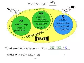
Optimizing Oil Recovery: CO2 Huff-n-Puff Process in New Mexico and Texas Reservoirs
This study evaluates the effectiveness of the CO2 Huff-n-Puff (H-n-P) enhanced oil recovery method in waterflooded carbonate reservoirs of New Mexico and Texas. The project aims to determine economic feasibility, provide industry guidelines, and enhance recovery efficiencies. Key findings suggest that the H-n-P process can mitigate early cash flow impacts, add reserves, and maximize recoveries in small fields, although economic challenges and operational limitations were noted. Long-term incremental oil production varies based on reservoir conditions, including gas saturation and water cut.

Optimizing Oil Recovery: CO2 Huff-n-Puff Process in New Mexico and Texas Reservoirs
E N D
Presentation Transcript
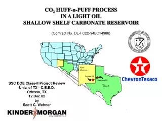
New Mexico Vacuum Fd. Slaughter Fd. Texas CO2 HUFF-n-PUFF PROCESSIN A LIGHT OILSHALLOW SHELF CARBONATE RESERVOIR(Contract No. DE-FC22-94BC14986) SSC DOE Class-II Project Review Univ. of TX - C.E.E.D. Odessa, TX 12.Dec.02 by Scott C. Wehner
NORTHERN SHELF Midland - Odessa
Generic Information Producing Horizon Grayburg & San Andres Fms Lithology Carbonate w/ few sands Heterogeneous Producing Interval 4,200 – 4,700 ft Avg. Net/Gross Pay Ratio 40/100 Reservoir Temperature 95o to 101o F Injection Pattern 40-A 5-Spot 20-A Line Drive Porosity Range (Avg.) 0 – 23.7 % (11.6%) Permeability Range (Avg.) 0 – 530 md (22.3 md) Reservoir Pressure Above Pb Oil Gravity 38o API Fractures Uncommon Production Drive Mature Waterflood
H-n-P Project Objectives • Determine whether oil can be recovered economically in a cyclic CO2 Huff-n-Puff process in a reservoir undergoing a waterflood/drive • Provide guidelines and transfer findings to the industry
Relation between Drive Index and Recovery Efficiency of the CO2 H-n-P Process Developed from Gulf-Coast sandstone reservoir field trials
Benefits of Wide Application if a Successful Process • Mitigate early negative cashflows in a CO2 flood • Add reserves associated with H-n-P CO2 process • Reduce LOE • Accelerate miscible CO2 process • Maximize recoveries in smaller fields • Maximize recoveries of acreage not targeted for miscible CO2 flooding • Provide early injectivity measures
Generalized CAPEX & Response Generalized CAPEX & Response Flood Starts 10 2 CO 8 Base WF MBOPD Miscible H-n-P 6 or 4 $MM 2 0 -3 -2 -1 0 1 2 3 4 5 6 7 8 9 10 11 12 13 14 15 16 17 18 19 20 21 22 23 24 25 Year
12 - 40 Days RESIDUAL OIL ~100 ft RESIDUAL OIL ~300 ft
1 - 4 Weeks RESIDUAL OIL RESIDUAL OIL . . . ABSORBING CO2
2 - 6 Months . . . MOBILIZES ACTIVE LOWER VISCOSITY WATERFLOOD . . . SWELLED OIL
Project Components • Reservoir Characterization and Geological Model • Parametric and Site-specific Simulation Study • Field Test • History-match of Field Test • Technology Transfer • Reservoir Characterization and Geological Model • Parametric and Site-specific Simulation Study • Field Test • History-match of Field Test • Technology Transfer
Typical H-n-P Performance (parametric simulation) • Peak oil rate is 2 to 5 times the base rate • Incremental oil of 1.5 to 3 MSTB for 25 MMscfCO2 • Peak oil rate returns to the base rate after 40 to 80 days • Incremental oil increases with injected CO2 volume
Typical H-n-P Performance (parametric simulation) • Incremental oil increases with watercut • WOR returns to the base level at the same time • Reservoir heterogeneity was not important. Results from 1, 2, 5, and 12 layer models were similar. • Trapped gas saturation was required for incremental oil
Typical H-n-P Performance (parametric simulation) • Oil Swelling, viscosity reduction, and near well pressure increase cause initial rise in oil rate but not long term incremental oil • Trapped gas causes long term incremental oil production. Without trapped gas, the oil production rate falls below the base rate after the initial peak because the H-n-P zone is being resaturated with oil
186 187 244 194 193 Site Specific 196 197 Reservoir DOE H-n-P Model 199 200 201 203 204 1 4-D, 3-C Seismic Central Vacuum Unit (CVU) (Excerpt)
INJECTION ! Injected ~50 MMscfCO2 ) Avg. 2.21 MMscfCO2/D ) Avg. 3.4o F ) Avg. 622 psig ! CO Containment 2 ! Bottomhole Pressure ! CO Breakthrough 2
SOAK 20-Day Soak ! Offset Injectors Activated ! Pressure Increased to 889 psig ! Cross-flow ? !
PRODUCTION ! Returned to Active Status ) Avg. 631 psig: 13-18/64" Chokes ) 400 - 900 Mscf/D ! Reduced H O Rate 2 ! 94% CO Gas Stream 2 ! Peak Oil impacted by Chockes/Artificial Lift ! Winter Weather Effects ! Wellbore Loading Gas Handling/Disposal
Slaughter Sundown Unit (SSU) (Excerpt) DOE H-n-P
Results/Conclusions • Sg (trapped) Appeared Non-existent in Demo • All injected gas recovered? • Oil production results mixed but lower thansimulations • Economically Challenged • Cannot support trucked/pumped CO2 • Pipeline creates options for consideration • Produced CO2 Disposal Not Always Available
Results/Conclusions • Economics burdened by costs to flow/pump wells • Restricting producing rate during flowback reduces recovery • H-n-P may provide indication of reduced H2O injectivity in miscible WAG operations • An estimate of CO2 injectivity can be found • H2O production can be reduced near-term
Results/Conclusions • LOE are reduced near-term • Oil response relates to CO2 volume • Higher H2O-cut provides better H-n-P response • Reservoir characterization not so critical • Don’t try this at home boys & girls…… it’s still R&D in SSC Waterflooded Reservoirs
One Lingering Question… Can the application of CO2 H-n-P cause an accelerated response from future CO2 miscible flooding?