Download
1 / 78
790 likes | 993 Vues
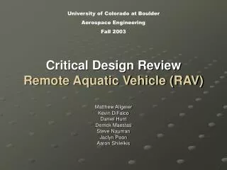
University of Colorado at Boulder Aerospace Engineering Fall 2003. Critical Design Review Remote Aquatic Vehicle (RAV). Matthew Allgeier Kevin DiFalco Daniel Hunt Derrick Maestas Steve Nauman Jaclyn Poon Aaron Shileikis. Presentation Outline. RFA’s and Changes since PDR

E N D
University of Colorado at Boulder Aerospace Engineering Fall 2003 Critical Design ReviewRemote Aquatic Vehicle (RAV) Matthew Allgeier Kevin DiFalco Daniel Hunt Derrick Maestas Steve Nauman Jaclyn Poon Aaron Shileikis
Presentation Outline • RFA’s and Changes since PDR • System Architecture • Subsystems Design Elements • Analysis • Mechanical Design • Electrical Design • Subsystems Testing & Verification • Integration Plan • Verification & Test Plan • Project Management Plan RAV CDR Presentation
RFA’s RAV CDR Presentation
Overview of Objectives • Mission Statement • The main objective for team RAV is to conceive, design, fabricate, integrate, verify and test a versatile proof of concept for a remotely controlled aquatic vehicle capable of both high speed, long range and low speed, short range maneuverability in challenging aquatic environments. • Objectives Summary • 3-axis High Speed Manueverability • Low Drag, High Speed & Long Range • 3-axis Low Speed Manueverability • Active Buoyancy • Yaw Rotation and Strafing • Small Size • Navigation of Challenging Obstacles • Ease of Deployment Logistics • Ease of Manufacturing • Specifications Derived from Facility, Monetary & Volume Limitations and Subsystems Requirements • Detailed Final Objective in Verification & Testing Section Test Illustration at Carlson Pool RAV CDR Presentation
Overview of Requirements • Structure • Pressure rated to 44 psi (20m Depth) • Buoyancy • Functional to 66 ft. (20 m) • RC Controllable to 2ft* Depth • Ascent/Descent Rate of 0.5 ft/sec* • Propulsion • 5 knots • Reversible • Variable speed • Low Speed Maneuvering (LSM) • Rotation Rate of 0.33 rev/min* • Minimal Drag during High Speed Maneuvering *changed from PDR RAV CDR Presentation
Overview of Mechanical Design RAV CDR Presentation
Overview of Electrical Design Subsystems RAV CDR Presentation
Hydrodynamics & Structure Buoyancy Propulsion LSM Communication Subsystems Design Elements RAV CDR Presentation
Hydrodynamic & Structural Analyses RAV CDR Presentation
Drag Reduction Flowchart RAV CDR Presentation
Hull Design • Myring Hull Contour Design [H1] • 3 compartments: • Nosecone • Mid-section • Tailpiece • Max outer diameter ≤ 6 in. • Tailpiece Machining Limitation • Aluminum 6061 Mid Section • Availability, Machinability, Cost & Strength • Mid-section • 24 in. long x 1/8 in. thick • Maximum Internal Volume • Mid-Section Passes Structural Compression Test Myring Hull Contour [H1] RAV Design RAV CDR Presentation
Nose Cone & Tailpiece Design • Nose Cone & Tailpiece designed using Myring Hull Contour Shape • Nosecone: 6 in. long • Tailpiece: 12 in. long • Nose Cone constructed of acrylic • Machine Shop Surplus of acrylic • Future Camera Use • Decreased Outer Diameter ≤ 6 in. • Tailpiece machinable “in-house” • Aluminum 6061 Tailpiece • Dissipate Heat from Motor • Final Total Drag • 16.1 N at 5 knots • Antenna deployed at 6 in. RAV Nose Cone RAV CDR Presentation
Control Surface Design • Control Surfaces for Trimming • Dive Planes size determined by Force difference between CB & CG • Rudder size determined by force from CG displacement from centerline • 4 Uniform Control Surfaces • Identical Design due to Horizontal and Vertical Trim Requirements • Manufacturing Ease • 4 Individual Servo’s • Motor Interference & Accessibility • Future Roll Control • Ideal Airfoil • Drag Polar Equation • Short Chord • Long Span RAV Tail Piece & Control Surfaces RAV CDR Presentation
Control Surface Sizing Conclusions • Selected NACA 0012 airfoil • Chord: 3 in. • Span: 3 in. long • 1/8 in. servo shaft • Control surfaces & servo shaft • Aluminum - excellent strength to weight ratios. • Servo selection • 15 deg. Control Surface deflection in 0.5 sec • Torque required 20.95 oz-in • Rated to 44.0 oz-in RAV CDR Presentation
Control Surface Sealing Design • Withstand Pressure = 45.0 psi • Dynamic Seals • Low Friction Servo Movement • SCLS Brass Linkage Seal • Small 0.39 in. x 0.59 in. length • Contains an O-ring to prevent water seepage • Seal will be pressed into tail section and sealed with epoxy to ensure no pressure leakage • 1/8 in. diameter stainless steel shaft will pass from servo to control surface • Coupler will be used to attach servo to shaft • Pins will be used to attach shaft to control surface Control Surface Sealing Design RAV CDR Presentation
Structural Verification and Test Plan Pressure/Sealing Verification • Description: Verify entire assembly can withstand pressures of ~45psi (20m depth) without leaking using a hyperbaric chamber. Accomplished by measuring pressure change inside. • Location: CSU hyperbaric chamber • Written confirmation obtained from Dr. Alan Tucker • Method and Measurements: • Increase pressure in hyperbaric chamber • Record pressure change inside hull • Test will be run at 45 psi for 30 minutes to correspond to the maximum amount of time the sub will be in the water for the Final Full-Systems Integrated Test. • Tests indicating pressure changes ≤ 0.2 psi will be considered a success • If failure occurs at ~45 psi it will be run again at 20 psi to ensure no leakage during pool tests • Analysis: • Pressure vs. Time inside and outside hull • Any pressure change greater than 0.2 psi indicates leakage • Sensors: PX236 Pressure Transducer (Omega) • Range: 0 – 60 psi • Bandwidth: 2 Hz • Resolution: 0.1 psi • Accuracy: +/- 1.5% RAV CDR Presentation
Buoyancy Analysis Inputs: RAV CDR Presentation
Buoyancy Mechanical Design • Johnson Electric Motor (12V) • High rpm (16,000 rpm@12V) • Lightweight (7.50 oz per motor) • Alexander Engel Gear Set • Proven for piston systems • Threaded Piston Rod • 6 mm • Piston Head • Aluminum • Machined in-house • Cylinder • Aluminum • Machined in-house • ID x OD x thickness: 2” x 2.25” x 0.125” • Batteries • 4 DuraTrax Receiver NiCd Flat Pack 6 Volt • 2200mAh (600mAh required per motor) • Length x Width x Height: 3-1/4“ x 1-3/4“ x 5/8" • Weight: 4.8 oz • Sealing • Precision Associates Inc. • Piston Head Seal • 75-1.840 1.84” ID x 0.075” C/S x 2.0” OD • End Cap Seal • 25-237 0.237” ID x 0.025” C/S x .287” OD Buoyancy Tanks RAV CDR Presentation
Buoyancy Electrical Design • Ballast Tank switch (BTS-II) • Proven system for remote submarines • Electronic (no servos) • Connects directly to Receiver • Stop-full micro switch • Stop-empty micro switch • Trim switch Buoyancy Electrical Schematic RAV CDR Presentation
Buoyancy Verification & Test Plan • Static Motor Strength Test (Feb 7th) • Verify System Produces force to operate at a depth of 20m • Horizontal Load Cell • Resolution: 1 lb • Range: 50 lb – 400 lb • Accuracy: +/- 1 lb • Expected Results: 141 lb force • Requirements: 140 lb force • Buoyancy Subsystem Test (April 5th) • Verify descent and ascent rate • Antenna Marking w/ Stopwatch • Range: 0 – 6 ft • Resolution: 0.5 ft • Expected Results: 3.0 ft/sec • Minimum Requirement: 0.5 ft/sec • Overall System Test (April 12th) • Verify system remains neutrally buoyant at given depth • PX236 Pressure Transducer • Range: 0 – 60 psi • Bandwidth: 2 Hz • Resolution: 0.1 psi • Accuracy: +/- 1.5% • Expected Results: 3.0 ft/sec with neutral buoyancy (< 0.2 psi change) • Minimum Requirement: 0.5 ft/sec with 1 minute neutral buoyancy [B1] RAV CDR Presentation
Propulsion Analysis RAV CDR Presentation
Major Components Motor BN28-36AF-01LH Dimensions Diameter = 2.25 inch Length = 3.6 inch Weigh: 46 oz Controller BDO-Q2-50-18 Dimensions L = 6.69 inch W = 3.54 inch H = 1.73 inch Weight: 13.76 oz NiMH Batteries 20 Cells 1.2 V/cell 2600 mAh Shaft Hardened steel Dictated by rotary shaft seal requirements Propeller 5.1 inch diameter 6.0 inch pitch Shroud (specs) Max outer diameter: 5.5 inches Min outer diameter: 5.22 inches Max inner diameter: 5.3 inches Min inner diameter: 4.62 inches Complex contour Mounting, accessories Mounting Motor to tail Shroud to tail Controller and batteries Bearing Ball bearing, double shielded Outer diameter: 5/8 inch Inner diameter: 1/4 inch 2nd point of contact for stability Rated to 52,300 RPM Bal Rotary Shaft Seal 71x model 60 psi 12,030 RPM Splined shaft Simplify assembly Propulsion Mechanical Design RAV CDR Presentation
Propulsion Electrical Design • BDO-Q2-50-18 • BN28-36AF-01LH • Closed loop feedback system RAV CDR Presentation
Propulsion Velocity Test 9.14 m Safety Net 22.86 m 24.62 m R AV • CU Carlson Pool • Diagonal will be used • Progressive testing • Trim • Increasingly faster • < 20 m to accelerate to 5 knots, 2.75 m/s • Required acceleration: 0.134 m/s2 • Sensors: Extech Mini-Anemometer • Range: 0.5 - 54.3 knots • Bandwidth: 3 Hz • Resolution: 0.3 knots • Accuracy: +/-(3% rdg+0.6 knots) • Data Collected • Distance vs. time • Velocity vs. time • Controlled Variables • Input voltage Pool Testing Diagram RAV CDR Presentation
LSM Analysis System design • 4 synthetic vortex jets actuated by solenoids • 8 jet configuration as alternative • Aluminum mount and solenoid housing • Permanently attached mount • Detachable housing • Latex diaphragm • O-ring seals • Circuit for control • 12V NiMH Batteries RAV CDR Presentation
LSM Drag Model Drag model for 4” diameter sub with 7” moment arm to rotate 2/3 rpm • Required Thrust = 0.0321 N • Required Moment = 0.5311 N*cm 4” sub test results: • Exp Moment = 0.4896 N*cm • Error = 7.8 % Drag model for 6” diameter sub with 9” moment arm to rotate 2/3 rpm (SF2) • Required Thrust = 0.2952 N • Required Moment = 5 N*cm Drag model for 6” diameter sub with 9” moment arm to rotate 1/3 rpm • Required Thrust = 0.0841 N • Required Moment = 1.523 N*cm [LSM1] RAV CDR Presentation
LSM Analysis D (Exit Diameter) L/D=4 L V2 V1 • Jet theory • L / D = 4 • Displaced volume (V1) = Exit volume (V2) • Thrust provided by jet • Required moment = 5 N*cm / jet • Moment vs. Frequency for various exit diameters • Requirements for 0.6” exit diameter to rotate 2/3 rpm: • Minimum frequency of 32Hz • Stroke length of 0.38” RAV CDR Presentation
LSM Solenoid Selection • Soft-Shift Solenoid • Slow, smooth motion with high starting force • Return spring available • Solenoid selection based on: • Size: 1.875” x 1.935” • Stroke: 0.400 ± 0.030” • Typical frequency at 50% duty cycle = 35 Hz • Stroke length deteriorates as frequency increases [LSM2] RAV CDR Presentation
LSM Mechanical Design • Solenoid • Spring loaded, Soft Shift • 12V, 24W at 50% duty cycle • Max frequency of 58Hz • .44 lbs • Housing • Aluminum or PVC • 0.35 lbs • Plungers • 2 mm thick • Mount • Aluminum (Welded to Hull) • 0.27 lbs • Sealing • O-rings (not shown) • Overall Weight ~1.06 lbs (excluding control circuit) • Final design pending (Exit Diameter) based on testing and optimization Solenoid Housing Plunger Mount LSM Exploded View RAV CDR Presentation
Control Electronic RC switch Oscillator Circuit Power 12V at 1500 mAh/jet NiMH batteries LSM Electrical Design [LSM3] RSGEX RC Switch Oscillator Circuit RAV CDR Presentation
LSM Verification and Test Plan Spin Rate Verification an Optimization • Description: Verify theoretical drag model with 4” sub. Using PVC model of RAV, different exit diameters and frequencies will be input, while the resulting rotational speed will be measured. Optimal exit diameter and frequency will be verified for final design. • Location: • CU Carlson Pool • Measurements and method: • Visually record and determine rotation rate • Analysis: • Plot rotational speed vs. frequency and exit diameter • Choose frequency and exit diameter which provide optimal thrust if different than theoretical model • Expectations: • Jets will be optimal for an exit diameter of 0.6” • Minimal frequency of actuation at 32 Hz • Sensors: • Digital camcorder and stop watch RAV CDR Presentation
LSM Verification & Test Plan LSM Test Matrix • Controlled Variables: • Exit diameter • Frequency • Resultants: • Moment generated by jets • Predictions: • Optimal exit diameter of 0.6” • Minimum frequency of 32 Hz RAV CDR Presentation
Communication Analysis RAV CDR Presentation
Communication Design • Futaba 8UAPS/8UAFS and matching FP-R148DP Receiver (FM/PCM 1024) • Free Loan from Aerobotics Research Laboratory – Budget Constraints • 8 Channels Available, RAV requires 7 • 0.75 W output • Receiver Power Gain Unknown • 72.330 MHz, ¼ wavelength whip antenna = 3.23 ft. long • Signal Loss at 72.330 MHz • Refraction Loss = 53.00 dB • Attenuation of Chlorinated Water = ~300 dB/m • Conductivity varies with Chlorine Concentration (Avg Value = 200 µMhos/cm) • Antenna Design • ¼ wavelength vertical antenna • Fiberglass Antenna Mast = 2ft. X 1/8 in. • Static Seal • Antenna Rise above Surface to avoid Losses • Run Propulsion Subsystems Test 6 in. below surface • Run to 75% Underwater Fail-Safe Depth for Full-Systems Integrated Test (if Tested) • Antenna Drag • 14.41 N at 7.5 knots • 6.40 N at 5.0 knots • Antenna Bending Moment • Conclusion • R/C not ideal for actual end goal – sufficient for Proof of Concept RAV CDR Presentation
Communication Test Plan • Range Test • Move away from RAV until Fail Safe Initiates • Distance Step Function • Stretch Goal - Repeat with RAV Underwater • Quantify Receiver Power Gain • Quantify Antenna Design Parameters RAV CDR Presentation
Data Acquisition • HOBO H8 4-Channel data logger • 32K • External Input Channel Measurement Range: 0-2.5 DC Volts • External Input Channel Accuracy: ±10 mV ±3% of reading • Boxcar software for analysis RAV CDR Presentation
Integration Plan • Drawing Tree • Purchased & Fabricated Parts • Assembly Flow Diagram • Order in which parts go together • Functional Test Plan (Subsystems Test Plans!!) • Test Parts • Test Assemblies • Identify Critical Path Elements • LSM Testing • Propulsion Ordering • Nosecone & Tailpiece Manufacturing • Facility Access • Hyperbaric Testing • Leak Testing • Buoyancy Static Test RAV CDR Presentation
Drawing Tree - Sample RAV CDR Presentation
Assembly Flow Diagram RAV CDR Presentation
Verification and Test Plan Full Integration Test Plan Description • At point A, dive to depth of 2.5 ft (0.5 ft/sec) • Remain Buoyant for 2 min • Accelerate to 3 knots and stop at point B • Rotate counterclockwise 90° (45 sec) • Accelerate to 2 knots and stop at point C • Rotate clockwise 270° (2.25 min) • Arrive at point D by maneuvering around obstacles using Buoyancy and LSM • Rotate counterclockwise 90° (45 sec) • Return to point A and surface using buoyancy • Repeat Testing Test Time = 10 min/Lap Location • CU Carlson Pool RAV CDR Presentation
Verification & Test Plan • Expectations: • All subsystems tests will be verified on fully integrated Sub • Top speed of 5 knots • Demonstrate active buoyancy • Rotational speed of 1/3 rpm • Sensors • Depth (Active Buoyancy) • PX236 pressure transducer • Speed • Extech mini-anemometer • Rotational Speed • Digital camcorder and stopwatch RAV CDR Presentation
Project Management Plan • Organizational Responsibilities • Work Breakdown Structure • Schedule • Budget • Specialized Facilities & Resources RAV CDR Presentation
Organization Chart RAV CDR Presentation
Work Breakdown Structure RAV CDR Presentation
MS Project Schedule RAV CDR Presentation
Task List - Sample LSM subsystem task list RAV CDR Presentation
Manufacturing & IntegrationTime Estimates RAV CDR Presentation
Budget RAV CDR Presentation
Specialized Facilities & Resources • CSU Hyperbaric Chamber • Dr. Alan Tucker (access granted in writing) • 150 ft. x 10 ft. • 67 psi • CU Carlson Pool • John Meyer (access granted in writing) • 25m x 12m x 1m • Aerobotics Laboratory • Cory Dixon (access granted in writing) • Aerospace Engineering Department & ITLL • Walt Lund, Trudy Schwartz, Matt Rhode & Bill Ingino • Testing Support Equipment RAV CDR Presentation
References • Fluid Mechanics • [1] Myring, D F. A Theoretical Study of Body Drag in Subcritical Axisymmetric Flow. Aerospace Quarterly. Volume 3. 1976. • Aerodynamics Book • Dynamics Book • Library Book • Buoyancy • [B1] www.subconcepts.com • Mr. Fred Grey, subconcepts.com • Propulsion • Argrow Paper • MooG (Co. Documentation) • LSM • [LSM1] http://scienceworld.wolfram.com/physics/CylinderDrag.html & http://astron.berkeley.edu/~jrg/ay202/node20.html#drag-coefficient & http://astron.berkeley.edu/~jrg/ay202/node21.html & www.eng.fsu.edu/~alvi/EML4304L/webpage/exp7description.doc • [LSM2] http://www.ledex.com • [LSM3] Robotics Sporting Goods • [LSM4] Murdock. Fluid Mechanics and its Applications. 1976. • AIAA Papers: 2001-2773. 2002-0124. 2002-0126. • Systems Engineer • Matt • Data Acquisition • Walt • Communications • ARRL Handbook • Shevell • Vable • Text Books: • Richardson. PADI Open Water Diver Manual. International PADI, Inc. 1999. • Burcher and Rydill. Concepts in Submarine Design. Cambridge University Press. 1994. • Robertson. Systems/Subsystems Investigation for a Multi-Sensor Autonomous Underwater Vehicle Search System. US Gov Agencies. April 1990. • Vable.l Mechanics of Materials. Oxford University Press. New York. 2002. • Shevell. Fundamentals of Flight (2nd Edition). Prentice Hall. New Jersey. 1989 • Cengel. Introduction to Thermodynamics and Heat Transfer. Irwin McGraw-Hill. 1997. • Reed. The ARRL Handbook for Radio Amateurs 2002.The American Radio Relay League, Inc. 2001 RAV CDR Presentation