Download
1 / 146
1.55k likes | 1.91k Vues
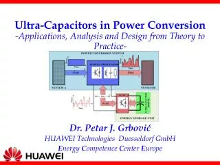
Ultra-Capacitors in Power Conversion -Applications, Analysis and Design from Theory to Practice-. Dr. Petar J. Grbović HUAWEI Technologies Duesseldorf GmbH E nergy C ompetence C enter E urope. Agenda. PART ONE: Background of Power Conversion & Energy Storage

E N D
Ultra-Capacitors in Power Conversion-Applications, Analysis and Design from Theory to Practice- Dr. Petar J. Grbović HUAWEI Technologies Duesseldorf GmbH Energy Competence Center Europe
Agenda • PART ONE: Background of Power Conversion & Energy Storage • PART TWO: Ultra-capacitor Energy Storage Device • PART THREE: Applications • PART FOUR: The Ultra-Capacitor Selection & Design • PART FIVE: Interface Power Converter
PART ONEBackground of Power Conversion & Energy Storage • The need for Energy Storage • Energy Storage Technologies & Devices • Electrochemical Batteries • Flywheel Energy Storage • Ultra-capacitor Energy Storage • Ultra-capacitors versus Batteries
The Need for Energy Storage • Electric systems A & B are interconnected via a power processor • A =the grid & B=electric drive • A= wind mill & B=the grid • A=the grid & B= a critical load (data center, hospital, etc., etc,.) • The power processor: a static power converter, transformer, installation, etc., etc. • The power processor has no energy storage capability • Instantaneous power of both systems are equal. • The system is oversized • Efficiency is reduced • Peak power penalty • Interruption cost and penalty
The Need for Energy Storage A power processor with energy storage capability • An energy storage device integrated within the power processor • The energy storage device decouples the system A from the system B • Instantaneous power • Average power of the systems A & B remains the same What is an energy storage device that can be used in power conversion applications?
Energy Storage Technologies & Devices • Electric energy storage device is a device with ability to store electric energy and keep it stored for undefined period of time • Direct Energy Storage (Simple electric devices), or • (Indirect Energy Storage) Complex electro-mechanical or electro-chemical devices
Energy Storage Technologies & Devices • CAES & HPES • Large scale utility applications • SMES • High power short term utility applications • Electrochemical Batteries • Long term, low & midium power applications • Flaywheels & Ultra-capacitors • Short term, low & midium power applications
Electrochemical Batteries • Secondary electrochemical batteries • Convert electric energy into chemical energy (charging), • Store chemical energy, and • Convert chemical energy into electric energy (discharging) • The most popular energy storage devices • Composed of: • Two electrodes of different material, and • Electrolyte • Electro-chemical action is a slow process • Charge and discharge rate are limited • Charge/Discharge power is limited • Life time and deep discharge cycling capability are limited
Electrochemical Batteries State of the art electro-chemical batteries
Ultra-capacitor Energy Storage • An ultra-capacitor is a special kind of electrostatic capacitor • It is not an electrochemical battery! • Energy is stored directly as electric field between two charged plates • Capacitance of hundreds up to thousands of [F] • The cell voltage ̴ 2.5 [V] • High energy density, 1 to 10 [Wh/kg] (>>> electrolytic capacitors ) • High power density 5 to 20 [kW/kg] • Fast charge/discharge • High cycling capability <500 000 [cycles] www.ultracapacitor.co.kr. • Wide range of operating temperature, from – 40 [ºC] up to +60 [ºC]
Flywheel Energy Storage • An electric motor/generator coupled with a large inertia rotor • Electric energy converted into mechanical and stored as kinetic energy of a rotating mass (speed ω0 and inertia J) • Low speed (<10 000rpm) and high (>100 000rpm) • High energy density • Fast charge/discharge , high peak power • Long life, high cycling capability • Wide range of operating temperature • Similar characteristics as ultra-capacitors • Efficiency of the motor/generator is a limiting factor
Ultra-capacitors versus Batteries • Size and cost of an energy storage • Energy Storage Capability • Power Capability & Conversion Efficiency • Cycling capability & Life time • If the charge/discharge time is shorter than TCR • An ultra-capacitor is the solution, • Otherwise an electro-chemical battery is the solution • Currently TCR =10 to 30s
PART TWOUltra-capacitor Energy Storage Device • A bit of history of ultra-capacitors • How does ultra-capacitor work • Material • Technologies overview • Advantages and disadvantages • Ultra-capacitor macro model • Charge and discharge Methods • Frequency dependent losses and thermal aspects • Integration of the ultra-capacitor into power conversion system • Ultra-capacitors today and tomorrow
Ultra-capacitor History • The double layer capacitor effect was described by Helmholtz in 1879 • Almost a century after that, a first ultra-capacitor was patented by Standard Oil Company in 1966 • A decade after NEC developed and commercialized this device in 1978 • The first high power ultra-capacitor was developed for military applications by the Pinnacle Research Institute in 1982 • Ten years after, in 1992, the Maxwell Laboratory had started development of DoE ultra-capacitors for hybrid electric vehicles • Today, the ultra-capacitors are commercially available from numerous manufacturers
How does ultra-capacitor work? • Ultra-capacitor is an electrochemical capacitor composed of: • Two current collectors • Two electrodes made of porous conducting material (activated carbon…) • A separator, and • Electrolyte • The electrodes are separated by the separator and immersed in the electrolyte One layer virtual capacitor One layer virtual capacitor
How does ultra-capacitor work? • Electrode is conducting and very porous material • Positive and negative ions form a layer attached to the electrode surface • Each layer forms a capacitor • The dielectric is a layer of ions. Relative permeability εR~10 • The dielectric thickness is d, diameter of the ions, approximately d~10 Å • Operating voltage is 1-3V, being limited by decomposition voltage of the electrolyte • The surface A is contact surface of the porous electrode, theoretically A~2000m2/g for activated carbon electrode • Theoretically, specific capacitance C~125F/g @ 2.5V 390kJ/kg • Overestimated capacitance, in reality it is 6 to 12F/g (5-10%)
How does ultra-capacitor work? • Simple double layer model is not accurate • Very first work, Helmholtz in 1853 • A layer of electrolyte molecules attached to the electrode • Overestimated capacitance, no voltage dependency • Gouy and Chapman, 1910 and few years later • Considered a space distribution of the charge • Stern, 1924 • Real dimension of solvent molecules • The space charge in two layers compact layer and diffused layer
How does ultra-capacitor work? • The porous electrode contact surface is overestimated • Theoretically A~2000m2/g for activated carbon electrode • Practically, 10 to 20 % of the theoretical one • The electrode pores are not uniform • Large pores • Medium, and • Small pores • Ions do not penetrate in medium and small pores. • The effective surface is much smaller than the theoretical one Zoomed in pore of porous activated carbon electrode. The ions penetrate only in large pores
Ultra-capacitor Material • Current collector • Metal foil (Al, etc., etc.) • Electrode • Carbon (Activated carbon, Carbon nanotubes, Fibers) • Metal oxides • Polymers • Electrolyte • Organic (Operating voltage ~2.8V, Good energy density, High series resistance, Low power density, External balancing circuit is required) • Aqueous (Operating voltage ~1V, Low series resistance, Good power density, Good voltage balancing even without external circuit) • Separator • Organic (Polymer, Paper)
Advanatges & Disadvanatges Advantages High specific power >10 [kW/kg] Low internal resistance High output power High cycling capability >500 000 [cycles] No chemical action Long life ~20 years Low cost per cycle Very high rate of charge/discharge Improved safety Simple charge/discharge method Disadvantages Low specific energy <10 [Wh/kg] for standard ultra-capacitors Voltage varies with state of charge Need for interface converter High self-discharge rate Low cell voltage. Need for series connection of cells into a module Low internal resistance may create an issue in case of short circuit
Ultra-capacitor Macro Model • Macro (Electrical) model • The control system analysis and synthesis, and • Losses calculation and thermal design • Two main effects • Voltage dependent capacitance • The charge time/space distribution due to porosity of the electrodes • Nonlinear transmission line • Nth order RLCG ladder network as an approximation • The inductance L and shunt conductance G (leakage ) neglected
Ultra-capacitor Macro Model • Nonlinear distributed network • Voltage dependent capacitance and resistance • Linearization around an operating point uC0=UC0 • Small signal Nth order ladder RC network • ESR RC0(ω) and capacitance CC0(ω) • Parasitic inductance is neglected at the frequency of interest An example: 2500F ultra-capacitor cell. The parameters at U0=1V
Frequency Dependent Capacitance and Energy Capability • The capacitance depends on frequency CC0(ω) • Is it reflected to a real application and how? • Specific energy depends on frequency (pulse width), Fig A • The capacitor is charged with a short pulse and a long pulse, Fig B • Final state of charge is expected to be the same in both cases , but it is not a case Specific energy versus pulse width Pulse width effect on final state of charge
Simplified Model • First order nonlinear RC model • ESR RC0 is assumed constant • The capacitance is voltage dependent • The ultra-capacitor current
Simplified Model Capacitance versus Voltage Capacitance & ESR versus Temperature
Simplified Model Leakage current modeled by a Shunt Resistor (4% @ T=72h) (2uA/F) Leakage current modeled by a Shunt Current Source
Simulation/Control Model Small Signal (Linear) Model Large Signal (Nonlinear) Model
Ultra-capacitor Energy Capability • Stored Energy • “Energetic” Equivalent Capacitance • Energy realized to the load • Specific Energy
Ultra-capacitor Energy Efficiency • Charging /Discharge Efficiency • Round Trip Efficiency
Ultra-capacitor Power & Current • Maximum Power • Maximum Power IEC 62391-2 • Maximum Specific Power • Maximum Specific Power IEC 62391-2 • Maximum 1s Current • Carbon Loading Capability
Frequency Dependent Losses • ESR RC0depends on frequency • Consider steady state operating voltage U0 • The system is linear (linearized) • However • If the current is sinusoidal • Instantaneous terminal voltage and power The capacitance C0=2500F at operating point U0=1V. Nominal voltage UC0=2.5V
Frequency Dependent Losses • Case A: • The current is periodic . • The terminal voltage and instantaneous power • Average power PAV over a period T Voltage and current The current spectrum
Frequency Dependent Losses • Case B: • The current is not periodic . • The terminal voltage and instantaneous power • Energy EESR determines the ultra-capacitor thermal image Voltage and current The current spectrum
Ultra-capacitor Thermal Model • Heat Generation • Irreversible heat generation, • Reversible heat generation • Thermal Equivalent Model • . Cell Thermal Model Simplified 1st order Model
Ultra-capacitor Thermal Model • Cell Temperature • A general case • A Very Short Pulse non-repetitive Pulse • A Very Long Pulse, or • A Train of Repetitive Pulses at High Frequency
Charge and Discharge Methodes • Constant voltage • The ultra-capacitor charge/discharged from/to voltage VBUS via a resistor R0 • The resistor is must, but not practical • Low efficiency • Constant current • Very common method in applications • Maximum discharge power and current Constant voltage charge/discharge circuit • Maximum charge power and current • limited by the current source terminal voltage U0max Constant current charge/discharge circuit
Charge and Discharge Methodes • Constant power • The most common method in applications • Maximum discharge power • If the power source exceeds maximum power, the voltage collapses • Maximum charge power is limited by the power source terminal voltage • Charge/discharge current (resistance RC0 is neglected) Constant power charge circuit
Ultra-capacitor Modules • Cell voltage is very low, not practical for power conversion application • N cells are series connected in a module, • M cells are parallel connected
Integration of the Ultra-capacitor into the Conversion System • The ultra-capacitor voltage varies with the state of charge (SOC) • If the ultra-capacitor is directly connected • The ultra-capacitor is oversized • Not cost and size effective • The conversion system voltage rating is N+1 • Not cost effective • Efficiency issue • Not convenient to directly connect the ultra-capacitor to the conversion system
Integration of the Ultra-capacitor & the Conversion System • The ultra-capacitor voltage has to be matched with the power processor dc bus voltage VBUS • An ideal transformer with variable gain M • Bidirectional “Loss-free” dc-dc converter emulates an ideal transformer • Topology of dc-dc converter in numerous variety
The Ultra-capacitors Today • Mature technology • Numerous products in mass-production • The cost is driven by the market, mainly automotive industry • The cost prediction for 2010 was 1.28US$ per kJ on cell level • The cost on module level >double • Packaging cost • Voltage balancing circuit cost • Significant cost reduction is expected • Development of high energy density devices • Higher capacitance • Higher cell voltage • Mass-production and application
The Ultra-capacitors of Tomorrow Development Objective • Energy density at least x10 of the existing (50Wh/kg to 100Wh/kg) • Lower internal resistance, <50% of existing • Higher power density • Higher cell voltage • Lower number of series connected cells into a string, higher reliability • Self balancing capability • No need for an external balancing circuit, lower complexity, lower cost, higher reliability • Higher operating temperature • >85ºC, >10 years life time • Strongly voltage dependent capacitance (Voltage-SOC characteristic ) • Smaller variation of the terminal voltage • Higher minimum discharge voltage , lower current rating, smaller interface dc-dc converter
The Ultra-capacitors in Development • Nano tube carbon electrode. Uniform pores and much higher effective surface. The concept developed at MIT [5] • Nano gate. The concept developed in Okamura Laboratory [6] • EesE, high voltage multilayer ceramic capacitor. The dielectric is high permittivity ceramic [7] • Mega Farad Ultra-capacitor. Additional thin layer of high permittivity material on top of the activated carbon electrode [8]
PART THREEApplications • Controlled electric drives • Renewable energy • Diesel electric generators • STATCOM and power quality • UPS • Traction drives
Application 1: Controlled Electric Drives • Electric drives convert electric energy into mechanical energy • Move an object • > 60% of total electricity production is consumed by electric drives • Numerous applications • Hoisting and lift applications • Machines with intermittent load • Blowers and Pumps Applications • Traction drives • Home appliance drives • The project “Application of ultra-capacitors in controlled electric drives” was sponsored by Schneider Toshiba Inverter, PacysurEure, Franca and the Laboratoired’Électrotechnique et d’Électronique de Puissance de Lille, l’EcoleCentrale de Lille, Villeneuve d’Ascq, France from 2007 until 2010.
Application 1: Controlled Electric Drives • Application issues • Braking energy • Dissipated on a brake resistor • 25 to 40% of consumed energy • Ride through capability • Critical in certain applications • 10kE up to 1ME per interruption • Ride through time up to 10 to 15s • High ratio of peak to average power • Peak power penalties • The installation size and cost • Voltage fluctuation and flickers Power profile of a 40 t Hoisting application Power profile of an intermittent load VSD
Application 1: Controlled Electric Drives A controlled electric drive with an ultra-capacitor as energy storage • Ultra-capacitor energy storage • To store and restore the drive braking energy • Low voltage ride through capability • To smooth the drive power • The ultra-capacitor is controlled independently from the motor control • As an option