Download
1 / 27
310 likes | 602 Vues
Measurement of the electron’s electric dipole moment. Mike Tarbutt Centre for Cold Matter, Imperial College London. Ripples in the Cosmos, Durham, 22 nd July 2013. -. 10 -22. Spin. Spin. +. Edm. Edm. 10 -24. MSSM. 10 -26. Multi Higgs. Left -Right. Either d e = 0, or T.

E N D
Measurement of the electron’s electric dipole moment Mike Tarbutt Centre for Cold Matter, Imperial College London. Ripples in the Cosmos, Durham, 22nd July 2013
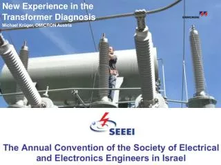
- 10-22 Spin Spin + Edm Edm 10-24 MSSM 10-26 Multi Higgs Left -Right Either de = 0, or T Other SUSY 10-28 Predicted values for the electron edm de (e.cm) 10-30 - T T CP implies 10-32 + 10-34 10-36 Insufficient CP Standard Model The electron’s electric dipole moment (EDM, de)
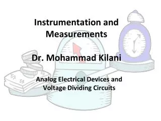
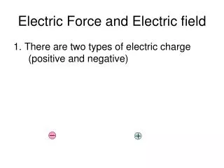
Measuring the EDM – spin precession B & E E Particle precessing in a magnetic field Particle precessing in parallel magnetic and electric fields Particle precessing in anti-parallel magnetic and electric fields Measure change in precession rate when electric field direction is reversed We use the valence electron in the YbF molecule
Eeff = FP Polarization factor Structure dependent, ~ 10 (Z/80)3 GV/cm We use a beam of YbF molecules Interaction energy =-de.Eeff Effective field, Eeff (GV/cm)
Simplified measurement scheme 1strf pulse E ±2 deEeff hf = 2mB ± B 2ndrf pulse Pulsed YbF molecular beam analyze spin direction
Result (2011) • 6194 measurements of the EDM, each derived from 4096 beam pulses • Each measurement takes 6 minutes • de = (-2.4 ± 5.7stat ± 1.5syst) × 10-28e.cm • | de | < 10.5 × 10⁻²⁸ e.cm (90% confidence level) Nature 473, 493 (2011)
g selectron 10-22 e e 10-24 MSSM 10-26 Multi Higgs Left -Right Other SUSY 10-28 Predicted values for the electron edm de (e.cm) 10-30 10-32 10-34 10-36 Standard Model Implications Excluded region gaugino Mass of new particle CP-violating phase For Ms= 200 GeVand qCP ≈1 => de ≈ 10-24 e.cm qCP< 10-3 ? Ms > 4 TeV ?
Some other electron EDM experiments With molecules: • ThO at Harvard \ Yale - new result anticipated with very high sensitivity • WC at Michigan – in development With ions: • HfF+ at JILA – trapped ion with rotating E & B fields, very long coherence times, being developed With atoms: • Trapped ultracold Cs at Penn State and U. Texas, being developed • Trapped ultracoldFr at Tohoku / Osaka, being developed With solids: • Gadolinium Garnets at LANL and Amherst – lots of electrons, but difficult to control systematic effects
d(m) 2×10-19 electron: neutron: d(p) 6×10-23 d(n) 3×10-26 d(e) 1×10-27 Particle EDMs - historic and present limits 10-20 s [d] (e.cm) 10-22 10-24 10-26 10-28 Year 1960 1970 1980 1990 2010 2020 2030 2000
CMSSM constraints from EDM measurements tan b = 3, MSUSY=500GeV M. Le Dall and A. Ritz, Hyperfine Interactions 214, 87 (2013)
Future experiments with YbF molecules Upgrades to existing experiment – x10 improvement (in progress) Molecular fountain of ultracoldYbF molecules (under development) x1000 improvement
Ben Sauer Jony Hudson Thanks... Jack Devlin Joe Smallman Dhiren Kara Ed Hinds
The YbF EDM experiment – schematic J. J. Hudson, D. M. Kara, I. J. Smallman, B. E. Sauer, M. R. Tarbutt & E. A. Hinds, Nature 473, 493 (2011)
E Eeff = FP Polarization factor Electric Field Atom / Molecule Structure dependent, ~ 10 (Z/80)3 GV/cm For more details, see E. A. Hinds, Physica Scripta T70, 34 (1997) Using atoms & molecules to measure de For a free electron in an applied field E, expect an interaction energy -de.E N.B. Analogous to interaction of magnetic dipole moment with a magnetic field, -m . B Interaction energy =-de.Eeff
E deEeff MF -1 0 +1 F = 1 -deEeff 170 MHz X 2S+ (n = 0, N = 0) Electric Field F = 0 Ground state YbF We measure the splitting 2deEeff between the MF = +1 and MF = -1 levels
Measurement scheme – a spin interferometer B rf pulse PMT F=1 Probe A-X Q(0) F=0 F=0 HV+ 3K beam Pulsed YbF beam HV- Pump A-X Q(0) F=1
B E E Measuring the edm with the interferometer Signal α cos2 [f/2] = cos2 [(mB B – de Eeff ) T / ћ] Counts
Modulate everything ±E ±B ±B spin interferometer ±rf1f ±rf2f ±rf1a Signal ±rf2a ±rf ±laser f 9 switches: 512 possible correlations • The EDM is the signal correlated with the sign of E.B • We study all the other 511 correlations in detail
Correcting a systematic error F = 1 E E F = 1 Stark-shifted hyperfine interval Stark-shifted hyperfine interval rf rf Imperfect E-reversal rf detuning F = 0 F = 0 Changes detuning via Stark shift phase shift: ~100 nrad/Hz Phase correlated with E-direction Correction to EDM: (5.5 ± 1.5) × 10-28e.cm
How to do better Electric field The statistical uncertainty scales as: Total number of participating molecules Coherence time
Cryogenic source of YbF • Produce YbF molecules by ablation of Yb/AlF3 target into a cold helium buffer gas • Helium is pumped away using charcoal cryo-sorbs • Produces intense, cold, slow-moving beams
Cold, slow beam of YbF molecules • Rotational temperature: 4 ± 1 K • Translational temperature: 4 ± 1 K Speed vs helium flow Molecules / steradian / pulse Flux vs helium flow Flow rate / sccm
Magnetic guide • Permanent magnets in octupole geometry, depth of 0.6 T • Separates YbF molecules from helium beam • Guides 6.5% of the distribution exiting the source
Laser cooling v’= 0 A2½ 0.3% 6.9% 92.8% Laser Laser 584 nm Excited state 568 nm 552 nm X2(N=1) v’’=2 Spontaneous emission Absorption v’’=1 v’’= 0 Ground state • Laser cooling is the key step!!
Simulations for YbF in an optical molasses 6 beams each containing 12 frequencies from 3 separate lasers – 750 mW total