Design and Software Architecture
Design and Software Architecture. Outline. What is design How can a system be decompose d into modules What is a module’s interface What are the main relationships among modules Software design techniques and i nformation hiding The UML collection of design notations


Design and Software Architecture
E N D
Presentation Transcript
Outline • What is design • How can a system be decomposed into modules • What is a module’s interface • What are the main relationships among modules • Software design techniques and information hiding • The UML collection of design notations • Design patterns • Architectural styles Ch. 4
What is design? • Activity that provides structure to any artifact: • Different domains: construction, mechanical systems, chemical systems, electrical systems • Different aspects: system design, hardware design, and software design • Decomposes system into parts, assigns responsibilities, ensures that parts fit together to achieve a global goal • Design refers to both an activity and the result of the activity Ch. 4
Two meanings of "design“ activity in our context • Activity that acts as a bridge between requirements and the implementation of the software • Activity that gives a structure to the artifact • Requirements specification document must be designed • must be given a structure that makes it easy to understand and evolve Ch. 4
The software design activity • Defined as system decomposition into modules • Produces a Software Design Document • describes system decomposition into modules • Often a software architecture is produced prior to a software design Ch. 4
Software architecture • Shows gross structure and organization of the system to be defined • Its description includes description of: • Main components of a system • Rationale for decomposition into its components • Relationships among those components • Constraints that must be respected by any design of the components • Guides the development of the design Ch. 4
Software architecture: an attempt to solve the problems of large systems Solution provided by Problems Software Architecture • Human’s inability in comprehending all the details of a project • The lack of standardsoftware design and development techniques • Legacy systems maintenance and evolution • Separation of Concerns, and high-level view of system • Design patterns, design for reuse, architectural styles • Software architecture recovery Ch. 4
Software Architecture definitions • A generally accepted definition: “The structure of the components of a program/system, theirinterrelationships, and principles and guidelines governing their design and evolution over time” [SEI 1994] • However, software architecture is more than “components and connectors”, or “major elements of a system”. It is a collection of views, patterns, stakeholders, and roles [SEI]. • Therefore, Software architecture provides the necessary means to formalize and interpret the properties of a system. Ch. 4
Software architecture terminology • Components: encapsulation of the system’s computation • Filter, layer, client, etc. • Connectors: encapsulation of interactions among components • RPC, event broadcast, pipe, etc. • Styles: definition of components & connectors, their properties, and configuration constraints that apply to all instances of a family of closely related systems • Pipe/filter, implicit invocation, client/server, etc. Ch. 4
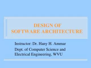
Transactions Bank Interface Component Diagram for ABM • Meaningful naming for services • Correct direction for the dependency arrows. Staff Operations User Interface Interface Dependency Ch. 4
See the brief guideline on how to design Component Diagram and Statechart at the architectural level of a systemin Lab 4 description Ch. 4
Important Aspects of Software Architecture • Architectural Styles • Architectural views • Architecture Description Languages • Architectural Analysis and Evaluation • Architecture Recovery Ch. 4
Architectural Styles • Styles: definition of components & connectors, their properties, and configuration constraints that apply to all instances of a family of closely related systems • Pipe/filter, implicit invocation, client/server, etc. • Assist in the construction of reliable, cost efficient, and understandable systems • Support reusability by capturing the common properties of a family of programs. • Styles can be implemented by the use of design patterns • Design patterns:are collections of structural and behavioral guidelines and rules for modelingfrequently occurring design decisions in large systems. Ch. 4
Sample Architectural Styles • Pipe and filter: UNIX shell • Client and server: distributed systems • Implicit invocation (Broker): CORBA, HP SoftBench • Layered: ISO/OSI reference model • Data repository (Blackboard): modern compilers, databases • Object-oriented: Aesop • Interpreter: programming languages • State transition: reactive systems • Main program and procedure: traditional systems • DSSA: avionics, C2, vehicle management Ch. 4
Filter Pipe Example: Pipes and Filters • Filters: components that receive a stream of input data, manipulate data, and produce a stream of output data. • Pipes: a sequential connector (file) that acts as a buffer of data between two filters and can provide parallel operations of filters. • Invariants: filters (components) must be independent entities; filters do not know the identity of their upstream and downstream filters • Common specialization: pipelines which restrict the topologies to linear sequences; bounded pipes which restrict the amount of data that can reside in a pipe; typed pipes which require the data passed between two filters have a well-defined type • A degenerate case: One filter processes all of its input data as a single entity • Examples: Unix shell programs; compilers • Advantages: clean design; support reuse; easy to maintain; permit specialized analysis (e.g. deadlock detection) support concurrency • Disadvantages: batch organization of processing (not interactive); difficult to synchronize pipes. Ch. 4
Different Architectural Styles Pipe & Filter Client & Server Implicit Invocation (Broker) Object Oriented State Transition Layered Main Program & Procedure Blackboard Ch. 4
Software Architecture views Views are the result of applying separation of concern on the development process to categorize the related knowledge about the system into manageable and understandable forms • Architectural views assist engineers in understanding, developing, and communicating different aspects of a software system. • Different groups of researchers have developed their own set of views • Two important examples: 4+1 views and Zachman framework. Ch. 4
Software Architecture views4+1 views • 4+1 View Model • Logical: functional requirement 2) Process: concurrency, distribution of system services 3) Deployment: planning, monitoring, reuse 4) Physical: network topology +1) Scenario: represents the sequence of system operations; it shows the relation among the elements of the 4 views: • Scenarios are represented by: object-interaction diagram, sequence diagram, collaboration diagram, statecharts. • Sometimes referred to as: use-case, or work flow. Ch. 4
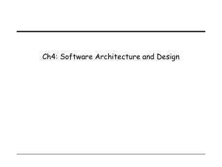
System integrators Performance Scalability Throughput 4 + 1 Architectural Views LogicalView Deployment View End-user Programmers Configuration management Scenario or Use Case View Functionality Process View Physical View System engineering System topology Communication Physical Conceptual Ch. 4 IBM Software Group | Rational Software
Scenario for telephone conversation in a PBX system • Figure shows a fragment of a scenario for the small PBX: • The controller of Joe’s phone detects and validate the transition from on-hook to off-hook and sends a message to wake up the corresponding terminal object. • The terminal allocates some resources, and tells the controller to emit some dial-tone. • The controller receives digits and transmits them to the terminal. • The terminal uses the numbering plan to analyze the digit flow. • When a valid sequence of digits has been entered, the terminal opens a conversation. Ch. 4
Views:Data viewFunction viewNetwork view Question:What the software How the software Where the Concern: Material FunctionalityLocation is made of? works?connections exist? Focus:Structure of dataData transformation Flow Descriptive Entity-Relation-Entity Input-Process-Output Node-Line-Node model: Software Architecture views: Zachman’s framework (Views& Perspectives) Zachman proposes a framework of views and perspectives that allows to map the knowledge about the system into non-overlapping representations provided by the framework. Views categorize the knowledge about the system into manageable and understandable forms. They answer to questions on: What, How, Where Ch. 4
Zachman’s framework (views &perspectives) Perspectives: Each perspective is a system documentation that reflects the interests of a different stakeholder in software development. • General scope: (Owner & business planer) • Description of gross estimation of the product’s features • Owner (Owner): • Representation of owner’s desires from the final product • Designer (architect): • Translation of owner’s representation to a technical plan • Developer(contractor): • Translation of designer’s plan to a feasible plan • Programmer (builder): • Actual production from a feasible plan Ch. 4
Zachman Views Framework Network view Data view Function view List of entities important to business General scope List of functions the business performs List of locations the business operates (Ballpark) Owner’s perspective Entity-relation diagram Function flow diagram Logistic network Designer’s perspective Perspectives Data flow diagram Distributed system architecture Data model (Architect’s plan) Developer’s perspective System architecture Data design Structure chart (Contractor’s plan) Programmer’s perspective Network architecture Data description Program (Builder’s product) Ch. 4
(MGR) (PREP) (OT) (ASM) (INV) Design Example: System Specification: This system controls different activities in a typical Fast-Food Restaurant, and consists of five communicating units: • Order-Taking unit. • Assembling unit. • Preparation unit. • Inventory unit. • Management unit. Ch. 4
Framework of different representations of restaurant sys. Ch. 4
General Scope (Perspective) Zachman’s Framework of Views and Perspectives Ch. 4
Data View (General Scope) • Fast-food restaurant system: • General Scope • Data view D1 Restaurant-menu, menu-items, orders,raw-materials, and recipes are the main data entities • Each orderconsists of menu-items. • Menu-items are selected from the restaurant-menu • Each menu-itemconsists ofraw-materials and the recipe Ch. 4
Fast-food restaurant system: • General Scope • Function view F1 Function View (General Scope) • Setting-up orders from restaurant-menu • Handling order payment • Distributing menu-items to be prepared • Assembling orders from the prepared menu-items • Keeping track of raw-material consumption • Setting-up different tables, prices, and recipes Ch. 4
Owner’s Perspective Zachman’s Framework of Views and Perspectives Ch. 4
(MGR) (PREP) (OT) (ASM) (INV) E-R diagram of the Restaurant System 3 • Restaurant-menu, menu-item (tables), order (tables),raw-material (table), and are the main data entities • Each orderconsists of menu-items. • Menu-items are selected from the restaurant-menu • Each menu-itemconsists ofraw-materials and the recipe 3 1 2 2 2 4 2 3 4
Function View (Owner’s Perspective) NOT IN EXAM • Setting-up orders from restaurant-menu • Handling order payment • Distributing menu-items to be prepared • Assembling orders from the prepared menu-items • Keeping track of raw-material consumption • Setting-up different tables, prices, and recipes Ch. 4
Network View (Owner’s Perspective) NOT IN EXAM Ch. 4
Aspects of Design Ch. 4
Two important goals • Design for change (Parnas) • designers tend to concentrate on current needs • special effort needed to anticipate likely changes • Product families (Parnas) • think of the current system under design as a member of a program family • Design the core part of a family of system Ch. 4
Sample likely changes? (1) • Algorithms • e.g., replace inefficient sorting algorithm with a more efficient one • Change of data representation • e.g., from binary tree to a threaded tree (see example) • 17% of maintenance costs attributed to data representation changes (Lientz and Swanson, 1980) Ch. 4
Example Ch. 4
Sample likely changes? (2) • Change of underlying abstract machine • new release of operating system • new optimizing compiler • new version of DBMS • … • Change of peripheral devices • Change of "social" environment • new tax regime • EURO vs national currency in EU • Change due to developmentprocess • transform prototype into product Ch. 4
Product families • Different versions of the same system • e.g. a family of mobile phones • members of the family may differ in network standards, end-user interaction languages, … • e.g. a facility reservation system • for hotels: reserve rooms, restaurant, conference space, …, equipment (video beamers, overhead projectors, …) • for a university • many functionalities are similar, some are different (e.g., facilities may be free of charge or not) Ch. 4
Design goal for family • Design the whole family as one system, not each individual member of the family separately Ch. 4
Sequential completion: the wrong way • Design first member of product family • Modify existing software to get next member products Ch. 4
Requirements Requirements Requirements 1 1 1 2 2 2 Version 1 3 Version 1 3 4 3 4 6 4 Version 1 Version 2 5 7 Version 3 5 Version 2 Sequential completion:a graphical view intermediate design final product Ch. 4
How to do better • Anticipate definition of all family members • Identify what is common to all family members, delay decisions that differentiate among different members • We will learn how to manage change in design Ch. 4
Module • A well-defined component of a software system • A part of a system that provides a set of services to other modules • Services are computational elements that other modules may use Ch. 4
Questions • How to define the structure of a modular system? • What are the desirable properties of that structure? Ch. 4
Modules and relations • Let S be a set of modules S = {M1, M2, . . ., Mn} • A binary relation r on S is a subset of S x S that is r S x S • If Mi and Mj are in S, then:<Mi, Mj> r can be written as Mi r Mj Ch. 4
Relations • Transitive closure r+ of r Mi r+ Mj iff Mi r Mj or Mk in S s.t. Mi r Mk and Mk r+ Mj (We assume our relations to be irreflexive) • r is a hierarchy iff there are no two elements Mi, Mj s.t. Mi r+ Mj Mj r+ Mi Ch. 4
Relations • Relations can be represented as graphs • A hierarchy is a DAG (directed acyclic graph) a graph a DAG Ch. 4