Download

1 / 42
910 likes | 3.11k Vues
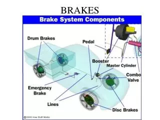
99. DRUM BRAKES. Figure 99-1 Typical brake system components showing disc brakes on the front and drum brakes on the rear. Figure 99-2 An exploded view of a typical drum brake assembly.

E N D
99 DRUM BRAKES
Figure 99-1 Typical brake system components showing disc brakes on the front and drum brakes on the rear.
Figure 99-2 An exploded view of a typical drum brake assembly.
Figure 99-3 The backing plate is the foundation of every drum brake. There are normally six pads where the brake shoes contact the backing plate.
TECH TIP: Quick-and-Easy Drum Brake Adjustment Check Tap the brake drum lightly with a hammer or wrench. If the brake shoes are not contacting the drum, the drum will ring like a bell. If the shoes are contacting the drum, the sound will be muffled.
Figure 99-4 A labyrinth seal is created between the lip of the backing plate and the groove in the brake drum.
Figure 99-5 A keystone anchor allows the brake shoes to self-center in the drum.
Figure 99-6 Piston stops prevent the wheel cylinder from coming apart.
Figure 99-7 Cross-section of a wheel cylinder that shows all of its internal parts. The brake line attaches to the fluid inlet. The cup extender prevents the cup seal lip from collapsing when the brakes are released.
Figure 99-8 The pushrods are held in place by the rubber dust boots. As the wheel cylinder pistons move outward, the pushrods transfer the movement to the brake shoes.
Figure 99-9 Steelbrake shoes are made from two stampings welded together—the web and the lining table.
Figure 99-10 Tapered ends on the linings help to reduce brake noise.
Figure 99-11 Typical drum brake shoe and the names of the parts.
Figure 99-12 The primary (forward facing) brake shoe often has a shorter lining than the secondary shoe (rearward facing). The color of the primary and secondary lining can also be different due to differences in friction and wear requirements.
Figure 99-13 Primary shoe lining may vary depending on the application.
Figure 99-14 Riveted brake linings are quiet and reliable at high temperatures.
Figure 99-16 Typical drum brake lining edge codes, showing the coefficient of friction codes for cold and hot circled.
CHART 99–1 Edge code letters represent a range of coefficient of friction of the linings.
TECH TIP: Purchase Quality Brake Linings for Best Performance While many brands of replacement brake lining provide acceptable stopping power and long life, purchasing factory brake lining from a dealer is usually the best opportunity to get lining material that meets all vehicle requirements. Aftermarket linings are not required by federal law to meet performance or wear standards that are required of original factory brake linings.
Figure 99-17 A typical drum brake assembly showing the support plate (backing plate), brake shoes, and springs.
Figure 99-18 A single spring-steel spring is used on some drum brakes.
Figure 99-19 Various types and styles of hold-down springs. The hold down pins are commonly called nails.
Figure 99-20 A mechanical brake linkage is part of most drum brake assemblies.
Figure 99-21 An aluminum brake drum with a cast iron friction surface. The cooling fins around the outside help dissipate the heat from the friction surface to the outside air.
Figure 99-22 Self-energizing action can increase or decrease the stopping power of a brake shoe.
Figure 99-25 A typical dual-servo brake adjusting link assembly commonly called a starwheel adjuster.
Figure 99-26 Dual-servo brake operation. The primary shoe on the left exerts a force on the secondary shoe on the right.
TECH TIP: Rear Wheel Lockup? Check the Adjustment Servo action enables a drum brake to provide increased stopping power, but it can also cause the brakes to grab and lock if they get too far out of adjustment. As clearance between the shoes and drum increases, the primary brake shoe is allowed a greater range of movement. The farther the shoe moves, the more speed it picks up from the rotating brake drum. At the moment the slack is taken up between the brake shoes, adjusting link, and anchor, the speed of the primary shoe is converted into application force by servo action. If the primary shoe is moving too quickly, it will apply the secondary shoe very hard and fast, causing the brakes to grab and possibly lock the wheels.
Figure 99-27 Dual servo action greatly increases the application force on the secondary shoe.
Figure 99-28 A cable-actuated starwheel adjuster. This type of adjuster makes the adjustment when the vehicle is being driven in reverse and the brakes are released.
Figure 99-29 A lever-actuated starwheel automatic adjuster. This type of adjuster makes the adjustment when the vehicle is being driven in reverse and the brakes are applied.
Figure 99-30 A link-actuated starwheel adjuster. This type of adjuster makes the adjustment when the brakes are released.
Figure 99-31 The operation of a typical self-adjuster. Notice that the adjuster actually moves the starwheel.
Figure 99-32 A cable-actuated starwheel adjuster with an overtravel spring.
Figure 99-33 A non-servo brake with a lever-actuated starwheel automatic adjuster on a leading shoe. This type of adjuster makes an adjustment as the brakes are applied.
Figure 99-34 A non-servo brake with a lever-actuated starwheel automatic adjuster on the trailing shoe. This type of adjuster makes the adjustment as the brakes are released.
TECH TIP: Cool the Brakes before Backing Self-adjusters can overadjust the rear drum brakes if the brake drums are hot and have increased in diameter due to the heat. For example, if a pickup truck towing a boat had to brake while backing down a long, steep grade to the boat ramp, the rear brake drums could become larger in diameter due to the heat created during braking. The brakes could overadjust if the driver repeatedly depresses and releases the brake pedal while backing the trailer down the boat ramp. Then, after the boat has been removed from the trailer and the rear brakes have cooled, the drums will shrink and keep the rear brakes from releasing, preventing the truck from moving up the ramp. NOTE: Some drum brakes are equipped with a bimetallic heat sensor that prevents the self-adjusters from working if the brakes are hot.