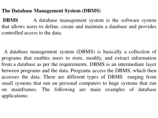
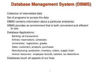
Database Management System (DBMS)
Database Management System (DBMS). Collection of interrelated data Set of programs to access the data DBMS contains information about a particular enterprise DBMS provides an environment that is both convenient and efficient to use. Database Applications: Banking: all transactions

Database Management System (DBMS)
E N D
Presentation Transcript
Database Management System (DBMS) • Collection of interrelated data • Set of programs to access the data • DBMS contains information about a particular enterprise • DBMS provides an environment that is both convenient and efficient to use. • Database Applications: • Banking: all transactions • Airlines: reservations, schedules • Universities: registration, grades • Sales: customers, products, purchases • Manufacturing: production, inventory, orders, supply chain • Human resources: employee records, salaries, tax deductions • Databases touch all aspects of our lives
Purpose of Database System • In the early days, database applications were built on top of file systems • Drawbacks of using file systems to store data: • Data redundancy and inconsistency • Multiple file formats, duplication of information in different files • Difficulty in accessing data • Need to write a new program to carry out each new task • Integrity problems • Integrity constraints (e.g. account balance > 0) become part of program code • Hard to add new constraints or change existing ones
Purpose of Database Systems (Cont.) • Drawbacks of using file systems (cont.) • Atomicity of updates • Failures may leave database in an inconsistent state with partial updates carried out • E.g. transfer of funds from one account to another should either complete or not happen at all • Concurrent access by multiple users • Concurrent accesses needed for performance • Uncontrolled concurrent accesses can lead to inconsistencies • E.g. two people reading a balance and updating it at the same time • Security problems • Database systems offer solutions to all the above problems
Levels of Abstraction • Physical level describes how a record (e.g., customer) is stored. • Logical level: describes data stored in database, and the relationships among the data. • type customer = recordname : string;street : string;city : integer;end; • View level: application programs hide details of data types. Views can also hide information (e.g., salary) for security purposes.
View of Data An architecture for a database system
Instances and Schemas • Similar to types and variables in programming languages • Schema – the logical structure of the database • e.g., the database consists of information about a set of customers and accounts and the relationship between them) • Physical schema: database design at the physical level • Logical schema: database design at the logical level • Instance – the actual content of the database at a particular point in time • Analogous to the value of a variable • Physical Data Independence – the ability to modify the physical schema without changing the logical schema • Applications depend on the logical schema • In general, the interfaces between the various levels and components should be well defined so that changes in some parts do not seriously influence others.
Data Models • A collection of tools for describing • data • data relationships • data semantics • data constraints • Entity-Relationship model • Relational model • Other models: • object-oriented model • semi-structured data models • Older models: network model and hierarchical model
Data Definition Language (DDL) • Specification notation for defining the database schema • E.g. create tableaccount (account-numberchar(10),balanceinteger) • DDL compiler generates a set of tables stored in a data dictionary • Data dictionary contains metadata (i.e., data about data) • database schema • statistics used for query optimization
Data Manipulation Language (DML) • Language for accessing and manipulating the data organized by the appropriate data model • DML also known as query language • Two classes of languages • Procedural – user specifies what data is required and how to get those data • Nonprocedural – user specifies what data is required without specifying how to get those data
SQL • SQL: most widely used language (combines procedural and declarative features) • E.g. find the name of the customer with customer-id 192-83-7465selectcustomer.customer-namefromcustomerwherecustomer.customer-id = ‘192-83-7465’ • E.g. find the balances of all accounts held by the customer with customer-id 192-83-7465selectaccount.balancefromdepositor, accountwheredepositor.customer-id = ‘192-83-7465’ anddepositor.account-number = account.account-number • Application programs generally access databases through one of • Language extensions to allow embedded SQL • Application program interface (e.g. ODBC/JDBC) which allow SQL queries to be sent to a database
Transaction Management • A transaction is a collection of operations that performs a single logical function in a database application • Transaction-management component ensures that the database remains in a consistent (correct) state despite system failures (e.g., power failures and operating system crashes) and transaction failures. • Concurrency-control manager controls the interaction among the concurrent transactions, to ensure the consistency of the database.
Entity-Relationship Model • The ER model is a very useful tool for designing databases • A database can be modeled as: • a collection of entities, • relationships among entities. • An entity is an object that exists and is distinguishable from other objects. • Example: specific person, company, event, plant • Entities have attributesExample: people have names and addresses • An entity set is a set of entities of the same type that share the same properties. • Example: set of all persons, companies, classes, accounts
Entity Sets customer and loan customer-id customer- customer- customer- loan- amount name street city number
Attributes • An entity is represented by a set of attributes, that is descriptive properties possessed by all members of an entity set. • Example: • customer = (customer-id, customer-name, customer-street, customer-city) loan = (loan-number, amount) • Domain – the set of permitted values for each attribute • Attribute types: • Simple and composite attributes (e.g., address). • Single-valued and multi-valued attributes • E.g. multivalued attribute: phone-numbers • Derived attributes • Can be computed from other attributes • E.g. age, given the date of birth
Composite Attributes • Attributes can have NULL values to denote: • Not applicable (phone number for a client that has no phone) • Missing values (there is a phone number but we do not know it yet) • Not known (we do not know whether there is a phone number or not)
E-R Diagram With Composite, Multivalued, and Derived Attributes
Degree of a Relationship Set • A relationship is an association among several entities • The degree refers to the number of entity sets that participate in a relationship set. • Relationship sets that involve two entity sets are binary (or degree two). Relationship sets may involve more than two entity sets. • Relationships between more than two entity sets are rare. Most relationships are binary. (More on this later.)
E-R Diagrams • Rectangles represent entity sets. • Diamonds represent relationship sets. • Lines link attributes to entity sets and entity sets to relationship sets. • Ellipses represent attributes • Double ellipses represent multivalued attributes. • Dashed ellipses denote derived attributes. • Underline indicates primary key attributes (will study later)
Cardinality Constraints • We express cardinality constraints by drawing either a directed line (), signifying “one,” or an undirected line (—), signifying “many,” between the relationship set and the entity set. • E.g.: One-to-one relationship: • A customer is associated with at most one loan via the relationship borrower • A loan is associated with at most one customer via borrower
One-To-Many Relationship • In the one-to-many relationship a loan is associated with at most one customer via borrower, a customer is associated with several (including 0) loans via borrower
Many-To-One Relationships • In a many-to-one relationship a loan is associated with several (including 0) customers via borrower, a customer is associated with at most one loan via borrower
Many-To-Many Relationship • A customer is associated with several (possibly 0) loans via borrower • A loan is associated with several (possibly 0) customers via borrower
Participation of an Entity Set in a Relationship Set • Totalparticipation (indicated by double line): every entity in the entity set participates in at least one relationship in the relationship set • E.g. participation of loan in borrower is total • every loan must have a customer associated to it via borrower • Partial participation: some entities may not participate in any relationship in the relationship set • E.g. participation of customer in borrower is partial
Alternative Notation for Cardinality Limits Cardinality limits can also express participation constraints
Roles • Entity sets of a relationship need not be distinct • The labels “manager” and “worker” are called roles; they specify how employee entities interact via the works-for relationship set. • Roles are indicated in E-R diagrams by labeling the lines that connect diamonds to rectangles. • Role labels are optional, and are used to clarify semantics of the relationship
Keys • A super key of an entity set is a set of one or more attributes whose values uniquely determine each entity. • A candidate key of an entity set is a minimal super key • Customer-id is candidate key of customer • account-number is candidate key of account • Although several candidate keys may exist, one of the candidate keys is selected to be the primary key. • Example: In the HKUST database, a student record has two candidate keys: HK ID and Student ID. Only one is chosen as the primary key (e.g., the Student ID).
Keys for Relationship Sets • The combination of primary keys of the participating entity sets forms a super key of a relationship set. • (customer-id, account-number) is the super key of depositor (see slide 20) • NOTE: this means a pair of entity sets can have at most one relationship in a particular relationship set. • E.g. if we wish to track all access-dates to each account by each customer, we cannot assume a relationship for each access. We can use a multivalued attribute though • Must consider the mapping cardinality of the relationship set when deciding the candidate keys
E-R Diagram with a Ternary Relationship • Suppose employees of a bank may have jobs (responsibilities) at multiple branches, with different jobs at different branches. Then there is a ternary relationship set between entity sets employee, job and branch
Binary Vs. Non-Binary Relationships • Some relationships that appear to be non-binary may be better represented using binary relationships • E.g. A ternary relationship parents, relating a child to his/her father and mother, is best replaced by two binary relationships, father and mother • Using two binary relationships allows partial information (e.g. only mother being known) • But there are some relationships that are naturally non-binary • E.g. works-on
Converting Non-Binary Relationships to Binary Form • In general, any non-binary relationship can be represented using binary relationships by creating an artificial entity set. • Replace R between entity sets A, B and Cby an entity set E, and three relationship sets: • 1. RA, relating E and A 2.RB, relating E and B • 3. RC, relating E and C • Create a special identifying attribute for E • Add any attributes of R to E • For each relationship (ai , bi , ci) in R, create • 1. a new entity eiin the entity set E 2. add (ei , ai ) to RA • 3. add (ei , bi) to RB 4. add (ei , ci ) to RC
Example of Conversion • Assume Ternary Relation Rb Ra Rc
Weak Entity Sets • An entity set that does not have a primary key is referred to as a weak entity set. • The existence of a weak entity set depends on the existence of a identifying entityset • it must relate to the identifying entity set via a total, one-to-many relationship set from the identifying to the weak entity set • Identifying relationship depicted using a double diamond • The discriminator (or partial key) of a weak entity set is the set of attributes that distinguishes among all the entities of a weak entity set. • The primary key of a weak entity set is formed by the primary key of the strong entity set on which the weak entity set is existence dependent, plus the weak entity set’s discriminator.
Weak Entity Sets (Cont.) • We depict a weak entity set by double rectangles. • We underline the discriminator of a weak entity set with a dashed line. • payment-number – discriminator of the payment entity set • Primary key for payment – (loan-number, payment-number)
Weak Entity Sets (Cont.) • Note: the primary key of the strong entity set is not explicitly stored with the weak entity set, since it is implicit in the identifying relationship. • If loan-number were explicitly stored, payment could be made a strong entity, but then the relationship between payment and loan would be duplicated by an implicit relationship defined by the attribute loan-number common to payment and loan
ISA (`is a’) Hierarchies name ssn lot Employees • Overlap constraints: Can Joe be an Hourly_Emps as well as a Contract_Emps entity? (Allowed/disallowed) • Covering constraints: Does every Employees entity also have to be an Hourly_Emps or a Contract_Emps entity?(Yes/no) • Reasons for using ISA: • To add descriptive attributesspecific to a subclass. • To identify entities that participate in a relationship. hours_worked As in C++, or other PLs, attributes are inherited. If we declare A ISA B, every A entity is also considered to be a B entity. hourly_wages ISA contractid Contract_Emps Hourly_Emps
ER Design Decisions - Attribute vs Entity • For each employee we want to store the office number, location of the office (e.g., Building A, floor 6), and telephone. • Several employees share the same office
ER Design Decisions - Entity vs Relationship • Account example • Can you see some differences? (e.g., can you have accounts without a customer?)
name dname ssn lot did Employees dname did budget Duration to from ER Design Decisions - Entity vs Relationship • You want to record the period that an employ works for some department. to from budget Departments Works_In2 name ssn lot Works_In3 Departments Employees
ER Design Decisions - Strong vs. Weak Entity • Example: What if in the accounts example (i) an account must be associated with exactly one branch (ii) two different branches are allowed to have accounts with the same number.
Relational Model - Tables • According to the relational model, the database stores relations (=tables). This is the most common model in commercial systems. • Our goal is to convert the ER diagram to a set of Tables The relation schema of the above relation is customer-schema = (customer-id,cust.-name, customer-street, customer-city) The actual table is a relation instance. Order of records in the table is not important. Duplicate records are NOT allowed.
Relational Model - Attributes • Each attribute of a relation has a name • The set of allowed values for each attribute is called the domain of the attribute (e.g., the domain for the student grades attribute would be {A+, A, A-,....}). • Attribute values must be atomic, that is, indivisible. Multivalued and composite attribute values are not allowed in tables, although they are permitted by the ER diagrams • The special value null is a member of every domain • The null value causes complications in the definition of many operations • we shall ignore the effect of null values in our main presentation and consider their effect later
Relational Databases • Storing all information as a single relation such as bank(account-number, balance, customer-name, ..)results in • repetition of information (e.g. two customers own an account) • the need for null values (e.g. represent a customer without an account) • That is why we need the ER diagrams (and some additional normalization techniques discussed later) to break up information into parts, with each relation storing one part.E.g.: account : stores information about accountsdepositor : stores information about which customer owns which account customer : stores information about customers
Reduction of an E-R Schema to Relations • Primary keys allow entity sets and relationship sets to be expressed uniformly as tables which represent the contents of the database. • A database which conforms to an E-R diagram can be represented by a collection of tables. • For each entity set and relationship set there is a unique table which is assigned the name of the corresponding entity set or relationship set. • Each table has a number of columns (generally corresponding to attributes), which have unique names. • Converting an E-R diagram to a table format is the basis for deriving a relational database design from an E-R diagram.
Composite and Multivalued Attributes • Composite attributes are flattened out by creating a separate attribute for each component attribute • E.g. given entity set customer with composite attribute name with component attributes first-name and last-name the table corresponding to the entity set has two attributesname.first-name and name.last-name • A multivalued attribute M of an entity E is represented by a separate table EM • Table EM has attributes corresponding to the primary key of E and an attribute corresponding to multivalued attribute M • E.g. Multivalued attribute dependent-names of employee is represented by a tableemployee-dependent-names( employee-id, dname) • Each value of the multivalued attribute maps to a separate row of the table EM • E.g., an employee entity with primary key 19444 and dependents John and Maria maps to two rows: (19444, John) and (19444, Maria)
Representing Weak Entity Sets A weak entity set becomes a table that includes a column for the primary key of the identifying strong entity set
Representing Relationship Sets as Tables • A many-to-many relationship set is represented as a table with columns for the primary keys of the two participating entity sets, and any descriptive attributes of the relationship set. • E.g.: table for relationship set borrower
Redundancy of Tables Many-to-one and one-to-many relationship sets that are total on the many-side can be represented by adding an extra attribute to the many side, containing the primary key of the one side E.g.: Instead of creating a table for relationship account-branch, add an attribute branch-name to the entity set account
Redundancy of Tables (Cont.) • For one-to-one relationship sets, either side can be chosen to act as the “many” side • That is, extra attribute can be added to either of the tables corresponding to the two entity sets • If participation is partial on the many side, replacing a table by an extra attribute in the relation corresponding to the “many” side could result in null values • The table corresponding to a relationship set linking a weak entity set to its identifying strong entity set is redundant. • E.g. The payment table already contains the information that would appear in the loan-payment table (i.e., the columns loan-number and payment-number).