Belle calorimeter upgrade
Belle calorimeter upgrade. B.Shwartz, on behalf of BELLE calorimeter group. Role of the electromagnetic calorimeter. Measurement of Energy/angle of photon (20MeV~8GeV) Electron identification K L detection together with KLM Redundant trigger Neutral trigger

Belle calorimeter upgrade
E N D
Presentation Transcript
Belle calorimeter upgrade B.Shwartz, on behalf of BELLE calorimeter group SuperKEKB 1st open meeting
Role of the electromagnetic calorimeter Measurement of • Energy/angle of photon(20MeV~8GeV) • Electron identification • KLdetection together with KLM • Redundant trigger • Neutral trigger Measurement of theluminosity • Online/offline luminosity SuperKEKB 1st open meeting
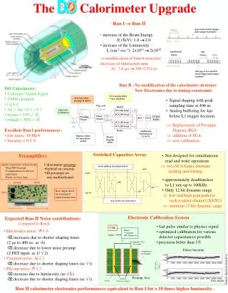
BELLE Electromagnetic Calorimeter for KEKB energy asymmetric B-factory Lcr = 30 cm = 16.2X0 Light output - 5000 ph.el./MeV electronics noise σ~200 keV 3 m Number of crystal: 8736 Total weight is ~43ton SuperKEKB 1st open meeting
Test beam BELLE calorimeter performance e+e The Belle calorimeter has been exploited from 1999 up to now. It demonstrates high resolution and good performance. SuperKEKB 1st open meeting
Calorimeter performance in a view of the luminosity increase. At L 1034cm-2s-1 and Ldt 700fb-1 Radiation damage of the crystals Increase of the PD dark current Small increase of thedark current in the barrel Essential increase of thedark current in endcaps Caused by neutron flux ( 1010 cm-2) In the most loaded part the light output degradation is about 10% Results in d 0.2-0.3 MeV, still not the most annoying problem. Basically – no problem. SuperKEKB 1st open meeting
Pile up effect Pile-up noise Fake clusters eg, MeV (E>20 MeV) 6 fake clusters,3 in barrel 3 in endcaps background SuperKEKB 1st open meeting
The obvious solution is to replace CsI(Tl) crystals by the other scintillators with L L CsI(Tl) , CsI(Tl)/10 and zero afterglowing. Lu2SiO5(Ce), LuAlO5(Ce), LaBr3(Ce) ……. ? Problems - cost and mass production We needed in a reasonable compromise… • To keep existing CsI(Tl) crystals in the barrel part. • To replace CsI(Tl) to pure CsI crystals in the end caps. • To modify all readout electronics. • To keep the present mechanical structure. SuperKEKB 1st open meeting
Modification of the electronics. • Pipe-line readout with waveform analysis: • 16 points within the signal are fittedby the signal function F(t):F(t) = Hf(t-t0) • Both amplitude (H) and time (t0) areobtained by the on-line shape fit: SuperKEKB 1st open meeting
Expected improvement Time information allows to suppress the fake clusters by 7 times for the barrel by rejecting wrong timeclusters. For endcaps the suppression factor is about 7 30 = 200due to the shorter decay time of the pure CsI The pileup noise will be reduced by factor 1.5 for barrel and factor 5 for endcaps: SuperKEKB 1st open meeting
New electronics New and new+ ECL electronics Very New electronics SuperKEKB 1st open meeting
Readout scheme for summer and autumn tests Obtained at the summer tests with cosmic rays ECL BE 1/8 (120 ch) Incoherent noises : 5.7 channels(330keV) (outer layers) 7.1 channels(410keV) (inner layers) 10% higher than expected Coherent noises : 1.2 channels(70 keV) for 16 channels (1 module) 0.6 channels(30keV) for 120 modules The time resolution per counter is 17/2=12ns as expected for 35 MeV energy deposition 8 Shaper digitizer were connected to ECL B3 sector (120 channels) Copper module installed in the crate near FB rack The Copper is readout by EFC PC roefc01 SuperKEKB 1st open meeting
A test of the new ECL electronics in the experiment Since beginning of this experiment (exp.67) up to Oct.23, morning, ECL was running with 120 channels (1/8 of the BE) connected to 8 new shaper-digitizer boards, read out by the copper module. Other ECL channels were in the usual status. In this configuration we collected about 965 pb-1 of the statistics. From this data 4 runs with 26 pb-1 was recorded without injection veto. On Oct.23, during the maintenance time, we replaced the new electronics with the old one. Nakamura-san analized the data from the local run performed after replacement and confirmed that all changed channels are alive. SuperKEKB 1st open meeting
6 4 First results over 1/8 of backward endcap new old Energy deposited in one crystal lg(E(MeV)) Shaded area – new electronics SuperKEKB 1st open meeting
Timing and background One channel time distribution SuperKEKB 1st open meeting
Injection study 150 ms HER HER new all events FE.and.BE bad inj.time LER all old SuperKEKB 1st open meeting
Current Status B.G. Cheon (Hanyang U) • A schematic design had been based on TKO version. • Some modifications were performed after the discussion with Y.Usov. • Purchase of all the parts was done in Oct. • Board layout (9U-size, 6-layers) was finished in Nov. • Schedule of the 1st prototype board production/test • PCB production : done in Nov. • Soldering : done in this week. • Basic test : 2 weeks (power line and analog part w/ pulse gen.) • Shipping to KEK : End of December (if no mistake is found) • Detail test : from Jan/2009 @ KEK • Revision of the board (production of the 2nd prototype) will take much short term because we already have all parts and much less effort is necessary.
Preamp Input shaper FADC analog processor & sum communication New VME Shaper board
Pure CsI in the end caps Properties of pure CsI and CsI(Tl) scintillation crystals • To use pure CsI crystals in the end caps we had to answer several important questions: • To find proper photodetector with a gain, large area and low capacity; • To prove the radiation resistance of the crystals; • To demonstrate the possibility to obtain the desirable characteristics. SuperKEKB 1st open meeting
Photodetector 2” UV sensitive photopentods(PP), Hamamatsu Photonics C 10 pF. PP gain factor 120-240. (we need > 30 in mag.eld) The gain factor drops down 3.5 times for B=15 kGs About 20-30 % improvement for angle 20-45 SuperKEKB 1st open meeting
Radiation hardness test with photons Radiation hardness of 4 pure CsI crystals(Kharkov) and one counter (pure CsI Crystal+ photopentode) were tested with gamma irradiation. For 15 krad dose the degradation of the lightoutput for 3 crystals and counter was less than 10%, but one counter lightoutput reduction was about 60% ( all crystals should be tested before assembling). Bremsstrahlung photons, E = 0 1.4 MeV from ELV-6, BINP Absorbed doses 0.250, 1 , 4 , 10 , 30 krad Neutron irradiation up to 1012cm-2 did not reveal a degradation within 5% SuperKEKB 1st open meeting
Counters design and properties • Electronics for pure CsI crystals are developed under the same general scheme as for the barrel part but: • shaping time is shorten to 30 ns; • clock frequency increases from 2 MHz to 43 MHz • The prototype of the shaper-digitizer module are developed, produced and demonstrated a good performance. SuperKEKB 1st open meeting
Are there alternatives for light readout and fast crystals? Nara W’s Uni group Ken Jery, FU JEN CATHOLIC UNIVERSITY Nara W’s Uni group SuperKEKB 1st open meeting
Summary • To keep good performance of the calorimeter at high backgroundconditions we need to upgrade the electronics for the barreland to replace both crystals and electronics in the endcaps . • The work for barrel electronics upgrade is in progress. The workingversion of the electronics has been developed. • At the next step we need ina detail test of the electronics integrated to DAQ of the Belle detector during the continuous run. • The prototype of the endcap calorimeter based on pure CsI counters with modifiedelectronics was tested with a beam and provided theexpected pile-up suppression. • More people are highly needed! • We are waitingfor a decision and budget to start the crystal and electronics production. SuperKEKB 1st open meeting
back up SuperKEKB 1st open meeting
Electronics modication(barrel) COmmon Pipelined Platform for Electronics Redout, Front-end INstrumentation Entity for Sub-detector Specific Electronics Contains boards (FINESSE) where the signal is processed Present status: for both, shaper-digitizer and COPPER (with FINNESE), prototypes have been tested and the expected parameters have been obtained. SuperKEKB 1st open meeting
Parameters determination FPGA are located at FINNESE module The algorithm of energy and time reconstruction was implemented. The online software allows: • To set preliminary sparsification threshold (before FPGA processing); • To set output sparsification threshold (after FPGA processing), before recording to • COPPER buffer; • To record amplitude, time and quality, reconstructed at FPGA; • To save raw sample informatin (amplitudes of 16 points) for each or some fraction of events. • According to simulation the algorithm works upto 50 kHz with occupancy < 1=3. SuperKEKB 1st open meeting
Beam test at BINP SuperKEKB 1st open meeting
Energy and time resolution results. -round points pure CsI -solid line MC -rectangles CsI(Tl) beam test The distributions are fit by convolution of the Compton spectrum and logarithmic-Gaussian. SuperKEKB 1st open meeting
Electronics modication(endcap) Present status: modules were developed and first prototypes have been tested SuperKEKB 1st open meeting
Summary of the new electronics tests and plans • System works and allows to record data from COPPER • The data evaluated by FINNESSE are consistent with that taken by the old electronics • The recorded data shows parameters close to expected. • Data quality vs. injection time are studied. A decrease of veto gate looks to be possible. Plans: • Further study pile-up noise suppression • To analyse data with sampling storage to get information about time noise correlation, as well as fit procedure and hardware reliability. • To analyse run without injection veto. • Implementation of the data from the new electronics to the standard data processing procedures: cluster reconstruction, Bhabha calibration etc. SuperKEKB 1st open meeting