Download
1 / 19
190 likes | 205 Vues
This study aims to generate a radiological baseline for INL by monitoring Cs-137 depth profile in surface soils. In situ measurements and advanced geostatistical methods are used to accurately identify areas with elevated Cs-137 levels.

E N D
A Comprehensive Study of the Depth Profile of Cs-137 in Surface Soils at the Idaho National Laboratory Monitoring and Surveillance Committee Meeting November 17, 2011 J. R. Giles, C. P. Oertel
Background • Soil monitoring data required to meet Federal (DOE) Environmental monitoring regulations • Soil monitoring data are an integral part of the radiological baseline for INL • Radiological baseline necessary for attracting new programs/projects • Radiological baseline data are used during emergency response for event mitigation • Data must be defendable
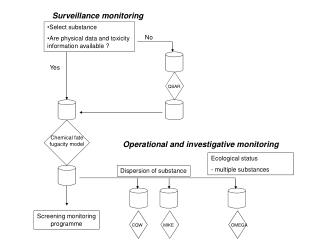
Monitoring Goals and Methodology • Goals: • Identify areas where Cs-137 > 0.23 pCi/g. Risk value of 1.0x10⁻⁶, the risk based concentration for a 30 year residential scenario • Build multiyear database in order to closely monitor any trends and provide measurement efficiency • Method: • Perform in situ measurements of Cs-137 • Use measured data to generate predicted Cs-137 at unmeasured locations • Use advanced geostatistical methods to refine measurement locations
Equipment Description • Standard Field Configuration: • n-type or p-type HPGe detector on tripod • 20-m diameter uncollimated field of view @ 1-m height • Data analysis performed using Environmental Measurements Laboratory M-1 Protocol (HASL-300)
Equipment Calibration • Calibration factor, Nf /Am(cts/s)/(pCi/g), is given by: Nf /Am = N0 /φ ∙ Nf /N0 ∙φ /Am Nf /Am= peak count rate per unit concentration N0 /φ = count rate per unit fluence rate at normalincidence –detector dependent Nf /N0 = angular correction factor at a given γ-ray energy– detector and source dependent φ /Am = fluence rate at detector per unit concentration–source dependent
Depth Distribution • Depth distribution described as α/ρ (cm2/g), where α is defined as the inverse of the relaxation depth. The relaxation depth is the depth at which the concentration is 1/e of the surface value (~37% of the surface concentration; ρ is the soil density. • Three common distributions: • Uniform – Typical of disturbed soil, α/ρ=0 • Planar – Typical of recent fallout, α/ρ=∞ • Exponential – Typical of aged fallout, 0<α/ρ<10
Soil puck collection • Soil puck samples collected at each sampling location. Samples are comprised of 10 subsamples, composited at 2.54 cm depth increments down to 30.5 cm, or refusal.
3-D Depiction of Soil Sampling Plan for the Determination of the Cs-137 Depth Profile
Geostatistical Methods Applied to INL Soil Monitoring Network • Basic Kriging with declustering applied to 2008 through 2010 data sets • Kriging error surfaces used to optimally locate sample points • 2011 data set large grid points were kriged and then error values analyzed using ESRI network densifier tool to produce new large grid locations for 2012 • Some INTEC points from 2011 were eliminated for 2012 based on localized kriging error surface • 2012 projected network is 248 points and is more spatially balanced