Download
1 / 31
310 likes | 329 Vues
This chapter covers the operation, types, and structures of semiconductor memories like RAM, DRAM, SRAM, and ROM. It delves into addressing methods, refreshing circuits, error correction, and advanced DRAM technologies. Key concepts such as static versus dynamic RAM, cache memory, and Synchronous DRAM (SDRAM) are explained in detail. The discussion includes types of ROM like Mask ROM, PROM, EPROM, EEPROM, and Flash memory, with emphasis on organization and performance considerations.

E N D
William Stallings Computer Organization and Architecture6th Edition Chapter 5 Internal Memory
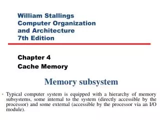
Organization • The basic element of a semiconductor memory is the memory cell. • All semiconductor memory cells share certain properties: • Exhibit two stable states (0 and 1) • Capable of being written into (at least once), to set the state. • Capable of being read to sense the state.
Memory Cell Operation Indicates read or write Select a memory cell for a read or write
Semiconductor Memory • RAM • Misnamed • ( all semiconductor memory is random access) • Read/Write • Volatile (揮發性) • Temporary storage • Static or dynamic
Dynamic RAM • Bits stored as charge in capacitors • Charges leak • Need refreshing even when powered • Simpler construction • Smaller per bit • Less expensive • Need refresh circuits • Slower • Main memory • Essentially analogue • Level of charge determines value
Dynamic RAM Structure 1.當address line為High時, Transistor為ON 2.當address line為Low時, Transistor為OFF
DRAM Operation • Address line active when bit read or written • Transistor switch closed (current flows) • Write • Voltage to bit line • High for 1 low for 0 • Then signal address line • Transfers charge to capacitor • Read • Address line selected • transistor turns on • Charge from capacitor fed via bit line to sense amplifier • Compares with reference value to determine 0 or 1 • Capacitor charge must be restored
Static RAM • Bits stored as on/off switches (flip flop) • No charges to leak • No refreshing needed when powered • More complex construction • Larger per bit • More expensive • Does not need refresh circuits • Faster • Cache • Digital • Uses flip-flops
Static RAM Operation • Transistor arrangement gives stable logic state • State 1 • C1 high, C2 low • T1 T4 off, T2 T3 on • State 0 • C2 high, C1 low • T2 T3 off, T1 T4 on • Address line transistors T5 T6 is switch • Write – apply value to B & compliment to B • Read – value is on line B
SRAM v DRAM • Both volatile • Power needed to preserve data • Dynamic cell • Simpler to build, smaller • More dense • Less expensive • Needs refresh • Larger memory units • Static • Faster • Cache
Read Only Memory (ROM) • Permanent storage • Nonvolatile • Applications of ROM • Microprogramming (see later) • Library subroutines • Systems programs (BIOS) • Function tables
Types of ROM • Mask ROM • Written during manufacture • Very expensive for small runs • Programmable (once) • PROM • Needs special equipment to program • Read “mostly” • Erasable Programmable (EPROM) • Erased by UV • Electrically Erasable (EEPROM) • Takes much longer to write than read • Flash memory • Erase whole memory electrically
Organisation in detail • The key design issues in semiconductor memories is the number of bits of data that may be read/written at a time. • W words of B bits each • Ex: A 16Mbit chip can be organised as 1M of 16 bit words • One-bit-per chip organization • Data is read/written one bit at a time. • A 16Mbit chip can be organised as a 2048 x 2048 x 4bit array • Reduces number of address pins • Multiplex row address and column address • 11 pins to address (211=2048) • Adding one more pin doubles range of values so x4 capacity
Refreshing • Refresh circuit included on chip • To disable the DRAM chip while all data cells are refreshing. • The refresh counter steps through all of the row values. • The data are read out & written back into the same location. • Takes time • Slows down apparent performance
Packaging An integrated circuit is mounted on a package that contains pins for connection to the outside world.
Module Organization 使用256K*1的DRAM組成 256K*8的記憶體模組
Module Organization (2)-1MB 256KByte
Error Correction • Hard Failure • Permanent defect • Soft Error • Random, non-destructive • No permanent damage to memory • Detected using Hamming error correcting code
Advanced DRAM Organization • Basic DRAM same since first RAM chips • Enhanced DRAM • Contains small SRAM as well • SRAM holds last line read (c.f. Cache!) • Cache DRAM • Larger SRAM component • Use as cache or serial buffer
Synchronous DRAM (SDRAM) • Access is synchronized with an external clock • Address is presented to RAM • RAM finds data (CPU waits in conventional DRAM) • Since SDRAM moves data in time with system clock, CPU knows when data will be ready • CPU does not have to wait, it can do something else • Burst mode allows SDRAM to set up stream of data and fire it out in block • DDR-SDRAM sends data twice per clock cycle (leading & trailing edge)
RAMBUS • Adopted by Intel for Pentium & Itanium • Main competitor to SDRAM • Vertical package – all pins on one side • Data exchange over 28 wires < cm long • Bus addresses up to 320 RDRAM chips at 1.6Gbps • Asynchronous block protocol • 480ns access time • Then 1.6 Gbps