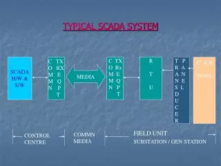
TYPICAL SCADA SYSTEM
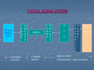
TYPICAL SCADA SYSTEM. C TX O Rx M E M Q N P T. R T U. T P R A A N N E S L D U C E R. C TX O RX M E M Q N P T. SCADA H/W & S/W. C & R PANEL. MEDIA. FIELD UNIT. COMMN MEDIA. CONTROL CENTRE. SUBSTATION / GEN STATION.

TYPICAL SCADA SYSTEM
E N D
Presentation Transcript
TYPICAL SCADA SYSTEM C TX O Rx M E M Q N P T R T U T P R A A N N E S L D U C E R C TX O RX M E M Q N P T SCADA H/W & S/W C & R PANEL MEDIA FIELD UNIT COMMN MEDIA CONTROL CENTRE SUBSTATION / GEN STATION
Instrumentation For SCADA • Transducers • RTU • Current Transformer • Capacitor Voltage Transformer
TRANSDUCER • Device converts one form of energy to another form. • Energy form viz. electrical, mechanical, chemical etc. • Transforms High level to Low level • Input – Hundreds of volt • Output – Few milliamperes • Measures field parameters like voltage, frequency, current, 3 phase bi directional active & reactive power and transformer tap position • Accuracy : +/- 0.2% class for frequency transducers and +/- 0.5% class for other transducers
TRANSDUCER • TYPICAL RATING Transducer Input Output Voltage 0-110 V 0-10 mA Current 0-1 Amp 0-10 mA 0-5 Amp Frequency 4-20 mA MW 4-12-20mA MVAR 4-12-20mA
Remote Terminal Unit • The RTU performs the data acquisition and supervisory control over the substation for the SCADA system. • As a minimum, the RTU collects, processes and transmits the data from the substation to the control-centers. • The following data are generally acquired from the sub-station:- Analog- Power, Reactive Power, Voltage, Frequency, Current. Digital- Circuit Breaker Status, Isolator Status,SOEs • The RTU also receives and processes digital and analog commands.
RTU: MAIN FUNCTIONS • SCADA • Local Control • Data Logging • Process Control
HARDWARE CONNECTIVITY DIAGRAM FOR SCADA AT SUBSTATION / GEN.STATION RS232 PORT TRANSDUCER PANEL REMOTE TERMINAL UNIT F R O M S W I T C H Y A R D - F I E L D P T SEC 110VAC TRANSDUCER I/P TERMINAL COMMN BOARD MAIN CPU BOARD PSU MW MVAR VOLT CT SEC 1 AMPS TRANSDUCER O/P TERMINAL A N A L O G I / P D I G T A L I / P C O N T R O L O/P EVENT LOGGER PANEL D R I V E R R E L A Y TERMINAL BLOCK TERMINAL BLOCK TERMINAL BLOCK
SCADA HARDWARE CONNECTIVITY WITH COMMUNICATION SYSTEM(PLCC) AT SUB-STN/GEN ST RTU N S K 5 modem RS 232 CONNECTIVITY PLCC T x / R x SPEECH / DATA PANEL PLCC INDOOR EQUIMENT
TRANSDUCERS • CLASSIFICATION • SELF POWERED/AUXILARY POWERED • INPUT • VOLTAGE/CURRENT/POWER/POSITION • OUTPUT • 0-10mA, 4-20mA, 0-5mA 0-5v,0-10v • OUTPUT IMPEDANCE • 500Ω,1000Ω,2000Ω • ACCURACY • 0.2 CLASS, 0.5 CLASS, CLASS 2 AND ABOVE
A/D CONVERSION AT RTU LEVEL(16 BIT ADC). FOR MW / MVAR TRANSDUCER: INPUT: PT SEC PHASE TO PHASE : 110VAC CT SEC TWO PHASE CURRENT (R & B): 1 AMPS. OUTPUT : 4 – 20mA(TRANSDUCER OUTPUT) IN ADC: AT 4mA = 6553 Count AT 20mA = 32767 Count 12mA IS THE CENTRE POINT. (+/- 0.1% IS THE ACCEPTABLE RANGE OF ERROR ON FULL SCALE) ( Ref Calculation Sheet for all type of Measurand)
TRANSDUCERS • Measures field parameters like voltage, frequency, current, 3 phase bi directional active & reactive power and transformer tap position. • Rating Vol: 110/115 volts phase to phase Current : 1 A Frequency: 45-55 Hz • Output : 4 – 20 ma / 500 ohms • External power supply • IEC 688 • Accuracy : +/- 0.2% class for frequency transducers and +/- 0.5% class for other transducers
SALIENT FEATURES OF ULDC RTU • A small rugged computer • CPU, volatile & non-volatile memory, power supply module, I/O module • Communication ports & maintenance ports • Allows the central SCADA master to communicate with the field devices • Acquires the data from the field devices/equipment and transfers the data to the SCADA system • Distributed Processing Technology • Main processor is 32-Bit 16Mhz and sub modules are 8-bit. • Real time clock • Access via PC-Based Configuration. • Password Protected. • Database configured via a PC and can be downloaded
SALIENT FEATURES OF ULDC RTU • Switch mode converter power supply module which provides power for mother board, VME cards, I/O modules and peripherals. Input voltage – 241 V AC, 50 Hz. Outpit voltage +/-5V DC, +/- 12 V DC, +/- 24 V DC • 32 Analog inputs per module ,15 bit resolution . • Conversion rate 660 ns for all 32 inputs. • 64 status inputs per status module,1ms scan time for 64 inputs,1ms SOE resolution. A simple status input/SOE input/accumulator input can be connected. LED indicators for each input. Contact wetting voltage supplied by power supply module. • 32 control output per control module. Two master relays for each output. One for close and one for trip. • Through the maintenance port, we can download the database, view data and Communications specific to each peripheral board and trouble shoot . • Advanced diagnostic capabilities • Time synchronisation of RTU done at every 1 minute.
Scan Cycles • All the analog data are scanned every 10/12 seconds • Status information are reported by exception • All status information are scanned for integrity check every 10 minutes • The SOE datas are time stamped at 1 ms resolution • Time synchronisation is done every 10 minutes
Current Transformer • A current transformer is a measurement device designed to provide a current in its secondary coil proportional to the current flowing in its primary . • The current transformer isolates measurement and control circuitry from the high voltages typically present on the circuit being measured . • Common secondary are 1 or 5 amperes. For example, a 4000:5 CT would provide an output current of 5 amperes when the primary was passing 4000 amperes .
Capacitor Voltage Transformer • Capacitor Voltage transformers (CVTs) are used for metering and protection in high-voltage circuits. They are designed to present negligible load to the supply being measured and to have a precise voltage ratio to accurately step down high voltages so that metering and protective relay equipment can be operated at a lower potential.
Basic Function Of the CVT HV • Where CHF is the equivalent rated capacitance for carrier communication * C1 : High Voltage capacitor * C2 : Intermediate Voltage Capacitor * C1 / C2 ratio is such that the required intermediate voltage can be achieved • L : Inductance of the choke which is designed to * Prevent carrier signals from flowing into the transformer circuit. * Resonate with the capacitor unit at 50 Hz which is the rated frequency. • D : Damping burden which is provided across one of the secondary windings to prevent terroresonance oscillations. • Tr : Transformer designed to provide the required output voltage at the desired burden Tr L C1 1a Metering CHF 1n 2a C2 Protection D 2n