Cam Design
Cam Design. ME 3230 R. R. Lindeke, PhD. Topics. We can simply say that CAM Design is a two part process: Design of the desired follower activity Design of the CAM profile (through follower inversion and tangent points)

Cam Design
E N D
Presentation Transcript
Cam Design ME 3230 R. R. Lindeke, PhD ME 3230
Topics • We can simply say that CAM Design is a two part process: • Design of the desired follower activity • Design of the CAM profile (through follower inversion and tangent points) • From a manufacturing prospective, CAM design and manufacturing is expensive since we desire high levels of accuracy to assure that the paths of the follows are precise and repeatable ME 3230
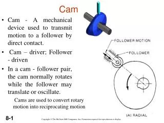
Cam/Follower Systems: As a designer we are concerned with follower path, Cam design and a spring to maintain contact between the Follower and the Cam ME 3230
Type of Follower Systems: ME 3230
Conceptual Cam System: employing a translating CAM or “unwound” rotating planer CAM From a design perspective we are dealing with “Dwells”, 1 or more “CAM Rises” and 1 or more “Cam Returns” that the follower will transit during the movement of the CAM through 1 cycle of motion ME 3230
Synthesizing Follower Motion: • Five types of Follower motion could be used: • Uniform Motion • Parabolic Motion • Simple Harmonic Motion • Cycloidal Motion • 5th Order Polynominal Motion • When we speak of, and design, CAM follower motion we are concerned with the transitional motion that occurs between specified or required movements or dwells (see figures 8.5 and 8.6)! ME 3230
Focus on Uniform Motion: • For a constant velocity cam, the segments between desired follower positions are connected by straight lines of constant velocity. • This is very simple to do but leads to a major issue in operation: • Infinite acceleration at each transition! • Infinite forces imposed of the follower and rapid cam system breakdown ME 3230
Parabolic Motion • The name doesn’t imply that the cam motion follows a parabola but it is 2nd order! • Velocity is either Trapezoidal or Triangular! • Acceleration is constant and controlled for “starting” and “stopping” follower motion (to inflection points in the transitions) • We design a ‘trajectory’ for the first half phase (with constant acceleration) and second half phase (with constant deceleration) for the transitions ME 3230
Parabolic Motion, cont. Called parabolic because the relationship between s (follower displacement and , CAM angle is 2nd order or parabolic! ME 3230
Parabolic Motion Problems: • Acceleration is controller, but the 3rd order derivative of position (jerk) is infinite at the beginning and ending point of each of the segments. • While not as damaging as infinite acceleration, infinite jerk can lead to vibratory system behavior. ME 3230
Developing Parabolic Motion: 2 solutions needed: Up to and After the inflection during the rise or return (1st half/2nd half thinking) • General Form: y = C0 + C1 + C22 • Velocity: y’ = C1 + 2C2 • Acceleration: y” = 2C2 • The constants are evaluated using boundary conditions (in initial half): • Considering that rise or return starts at an initial CAM angle position, =0; y=y’=0 then C0 & C1 = 0 • Let = cam rotation during transition L = total rise or return amount: at = /2, y = L/2 then C2 = (2L/ 2) ME 3230
Developing Parabolic Motion: 2 solutions needed up to and after the inflection during the rise or return (2nd half) • The constants are evaluated using boundary conditions (initial half): • Considering that the CAM angle position as we begin the 2nd half of the transition is = /2 and y=L/2 then C0 = -L • While At = y = L and y’ = 0 • C1 = (4L/ ) • and C2 = -(2L/ 2) • We have two operating regimes with (slightly) different controlling equations for position (y) velocity (y’) and acc. (y”) • These are solved (to 4th place accuracy of y) as is incremented to build the follower transition model ME 3230
Try one: • Yfollower moves from 0 to .75” (L) while a CAM rotates from =15 to 75 ( = 60 and = -15) using a parabolic profile (cam rotational velocity = 360/s) • 1st half: • 2nd Half: ME 3230
Follower Trajectory: ME 3230
Harmonic Follower Trajectories: • The type of motion generated in an offset radial follower by an eccentric circular cam • The motion is characterized as: • (for rise): y = C0 + C1Cos(C2) = C0(1+(C1/C0)Cos(C2) • From initial to = (and y = initial value to L), continuously defined! • This motion exhibits • No discontinuity at the transition point • A sinusoidal velocity equation • A cosinusoidal acceleration equation • A sinusoidal jerk equation ME 3230
Harmonic Rise Eqns. (y = 0 at =0 to = at y=L) Jerk is still infinite at the very ends of transition because acceleration at the interval ends is not zero but jerk can be computed within the transition! ME 3230
Harmonic Return Eqns. (y = L at =0 to = at y=0) Note: Change in Signs (otherwise the equations are identical!) ME 3230
Harmonic Return Eqns. (y = .75 at =75 to y=0at =135) (subs -75 for ) • CAM Vel.: 360/s, at = 74.99999, Acc = 0 ME 3230
Cycloidal Motion – a continuous path method but where we have zero acceleration at beginning and end of trajectory and controlled jerk • These trajectories have sinusoidal acceleration curves so are at 0 at the start! • Curves computed are valid from = 0 to = ME 3230
Cycloidal Motion – Symmetrical Rise and Return! • While for returns: • yret = L – ycomp • y’ret = -y’ • y”ret = -y” • y’”ret = -y’” Models of actual motion can be easily computed using Spreadsheets and the accuracy of the Cam that results is a function of the level of the angular resolution for the cam and the ability to machine the desired profile ME 3230
General (5th order) Polynomial Follower trajectories • We begin with boundary conditions for Position, Velocity AND Accelerations at each end of a desired transition • The General Model of Follower Motion is, (with 6 BC’s n=5): • General Vel. & Acc. Equations considering relative CAM rotations: ME 3230
General Polynomial Models Cont: • If the CAM operates at a constant velocity: • d/dt = • d2/dt2 = 0 • At = 0; y, ydot and yd.dot = 0 • At = ; y = L; ydot and yd.dot = 0 • Allows us to built the 6 term model: ME 3230
Using the Boundary Conditions: • C0=C1=C2=0 • C3=10L • C4=-15L • C5=6L • This leads to the so-called “10-15-6” models (so named because of the coefficients that remain in the follower position model) ME 3230
Polynomial Motion Characteristics: • Jerk is Parabolic (2nd order in CAM angular displacement)! • We have accurate solutions for position, velocity, acceleration and jerk • The CAM profile geometry can be easily computed for CNC programming of a cam mill using spreadsheets • The degree of accuracy for the transitions is a function of the refinement of the CAM angle ratio (/) ME 3230
Lets Try Yfollower moves from 0 to .75” (L) while a CAM rotates from 15 to 75 ( = 60 and = -15) = 360/s constant … Continues to 75 by 1 increments ME 3230
Lets Try Yfollower moves from 0 to .75” (L) while a CAM rotates from 15 to 75 ( = 60 and = -15) = 360/s constant ME 3230
With Velocity: ME 3230
With Acceleration: ME 3230
And With Jerk: ME 3230