Broadcast Networks and Channel Allocation Protocols
600 likes | 639 Vues
Learn about broadcast networks, channel allocation, multiple access protocols, and MAC sub-layer in LANs. Understand dynamic channel allocation technologies and collision-free protocols.

Broadcast Networks and Channel Allocation Protocols
E N D
Presentation Transcript
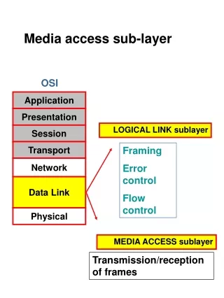
Media access sub-layer OSI Application Presentation LOGICAL LINK sublayer Session Transport Framing Error control Flow control Network Data Link Physical MEDIA ACCESS sublayer Transmission/reception of frames
Broadcast Networks Single communication channel that is shared by all the machines on the network computer General Rule: Smaller, geographically localized networks 1 2 3 4 5 cable Packets Short messages sent by any machine are received by all others Address Quick Review… Fields
Packets 1 2 3 4 5 3 ALL machines receive it, but one processes it Also possible to address a packet to ALL machines (special code in the address field) Mode of operation: Broadcasting Also possible to address a packet to a SUBSET of machines (group number code in the address field) Mode of operation: Multicasting Quick Review…
The Medium Access Sublayer deals with BROADCAST NETWORKS AND THEIR PROTOCOLS 4.1 THE CHANNEL ALLOCATION PROBLEM 4.2 MULTIPLE ACCESS PROTOCOLS IEEE STANDARD 802 FOR LANs DATALINK SWITCHING VLANs
The Channel Allocation Problem Central theme How to allocate a single broadcast channel among competing users? Static FDM /TDM (Frequency/Time Division Multiplexing) FDM : Radio/TV broadcasts TDM : POTS (Plain Old Telephone System) GSM uses both (Global System for Mobile Communications) Wasteful of bandwidth Dynamic Pure/ Slotted ALOHA Carrier Sense Multiple Access (CSMA) Protocols Collision free protocols
Dynamic Channel Allocation Technologies Pure ALOHA Slotted ALOHA CSMA CSMA/CD (old ETHERNET) Switching (Fast ETHERNET) Token passing (Token Ring )
ALOHA Protocols Anyone may transmit whenever they want. (Continuous time model.) Each radio detects collisions by listening to its own signal. A collision is detected when a sender doesn't receive the signal that it just sent. After a collision, wait a random amount of time and transmit the same frame again. This technique is known as backoff. Back in 1970, the University of Hawaii built a network out of radios that broadcast signals. Basic idea:
Slotted ALOHA Time is divided into slots… can only transmit at start of slot Vulnerable period halved => max. efficiency is doubled Requires sync of clocks Still poor at hi-loads
Carrier Sense, Multiple Access (CSMA) We can improve the performance of our simple network greatly if we introduce carrier sensing (CS). With carrier sensing, each host listens to the data being transmitted over the cable. A host will only transmit its own frames when it cannot hear any data being transmitted by other hosts. When a frame finishes, an interframe gap of about 9.6sec is allowed to pass before another host starts transmitting its frame. Communication Link
Carrier Sense Multiple Access (CSMA) Improves performance when higher medium utilisation When a node has data to transmit, the node first listens to the cable (using a transceiver) to see if a carrier (signal) is being transmitted by another node.
CSMA with Collision Detection CSMA/CD can be in one of three states: contention, transmission, or idle.
IEEE 802.3: CSMA/CD Bus LAN The 802.3 standard describes the operation of the MAC sub-layer in a bus LAN that uses carrier sense, multiple access with collision detection (CSMA/CD). Beside carrier sensing, collision detection and the binary exponential back-off algorithm, the standard also describes the format of the frames and the type of encoding used for transmitting frames. The minimum length of frames can be varied from network to network. This is important because, depending on the size of the network, the frames must be of a suitable minimum length. The standard also makes some suggestions about the type of cabling that should be used for CSMA/CD bus LANs. The CSMA/CD Bus LAN is also widely called Ethernet.
Ethernet MAC Sublayer Protocol Frame formats. (a) DIX Ethernet, (b) IEEE 802.3.
IEEE 802.3: MAC Addresses Every network card in the world has a unique 46-bit serial number called a MAC address. The IEEE allocates these numbers to network card manufacturers who encode them into the firmware of their cards. The destination and source address fields of the MAC frame have 48 bits set aside (the standard also allows for 16-bit addresses but these are rarely used). The most significant bit is set to 0 to indicate an ordinary address and 1 to indicate a group address (this is for multicasting, which means that frames are sent to several hosts). If all 48 bits are set to 1 then frames are broadcast to all the hosts. If the two most significant bits are both zero then the 46 least significant bits contain the MAC addresses of the source and destination hosts.
IEEE 802.3: Minimum Frame Length When a host transmits a frame, there is a small chance that a collision will occur. The first host to detect a collision transmits a 48-bit jam sequence. To ensure that any hosts involved with the collision realise that the jam sequence is associate with their frame, they must still be transmitting when the jam sequence arrives. This means that the frame must be of a minimum length. The worse case scenario is if the two hosts are at far ends of the cable. If host A’s frame is just reaching host B when it begins transmitting, host B will detect the collision first and send a jam signal back to host A.
CSMA/CD Minimum Ethernet Frame Size • To ensure that no node may completely receive a frame before the transmitting node has finished sending it, Ethernet defines a minimum frame size (i.e. no frame may have less than 46 bytes of payload). • The minimum frame size is related to the distance which the network spans, the type of media being used and the number of repeaters which the signal may have to pass through to reach the furthest part of the LAN. • Together these define a value known as the Ethernet Slot Time, corresponding to 512 bit times at 10 Mbps.
IEEE 802.3: Minimum Frame Length The longest time between starting to transmit a frame and receiving the first bit of a jam sequence is twice the propagation delay from one end of the cable to the other. This means that a frame must have enough bits to last twice the propagation delay. The 802.3 CSMA/CD Bus LAN transmits data at the standard rate of r = 10Mbps. The speed of signal propagation is about v = 2108m/s.
IEEE 802.3: Minimum Frame Length In order to calculate the minimum frame length, we must first work out the propagation delay from one end of the cable to the other.
IEEE 802.3: Minimum Frame Length The standard frame length is at least 512 bits (64 bytes) long, which is much longer than our minimum requirement of 64 bits (8 bytes). We only have to start worrying when the LAN reaches lengths of more than 2.5km. 802.3 CSMA/CD bus LANs longer than 500m are usually composed of multiple segments joined by in-line passive repeaters, which output on one cable the signals received on another cable. When we work out the minimum frame length for these longer LANs, we also have to take the delays caused by the passive repeaters (about 2.5sec each) into account as well.
Shortest Ethernet Frame Why specify a shortest frame of 64byte? • 64 bytes sent at 10Mbps 51.2sec • 500m/segment, 4 repeaters between nodes 2500m25 sec propagation delay • The frame should be longer enough for sender to detect the collision(2x25 or about 50 sec ) Node A R1 R2 R3 R4 Node B 500m 25 sec propagation delay
IEEE 802.3: Non-Deterministic The 802.3 CSMA/CD bus LAN is said to be a non-deterministic network. This means that no host is guaranteed to be able to send its frame within a reasonable time (just a good probability of doing so). When the network is busy, the number of collisions rises dramatically and it may become very difficult for any hosts to transmit their frames. A real-time computing application (such as an assembly line) will demand that data is transmitted within a specified time period. Since the 802.3 bus LAN cannot guarantee this, its use for real-time applications may not only be undesirable but potentially dangerous in some situations.
Ethernet 10Base-T & 100Base-TX • Wiring • Unshielded Twisted Pair (UTP) • Category 5 wiring is best • Cat 3 and Cat 4 in some older installations • Bundle of eight wires (only uses four) • Terminates in RJ-45 connector
10Base-T & 100Base-TX hubs • UTP-based networks use hubs to interconnect NICs • each UTP cable runs directly from a NIC to a hub
10Base-T & 100Base-TX hubs • Hubs have many ports, each of which has one incoming network cable • Hubs are usually located in computer rooms, or network distribution cupboards • a patch panel (or patch bay) is used to connect between hubs and the wall sockets throughout a building
10Base-T & 100Base-TX wiring • Wiring • 100 meters maximum distance hub-to-station • Can use multiple hubs (max 4) to increase the distance between any two stations 200 m 100 m 100 m
10Base-T to 100Base-TX • Upgrading from 10Base-T to 100Base-TX • Need new hub • May have some 10 Mbps ports to handle 10Base-T NICs • May have autosensing 10/100 ports that handle either • Need new NICs • Only for stations that need more speed • No need to rewire • This would be expensive
Multiple Hubs in 10Base-T • Farthest stations in 10Base-T can be five segments (500 metres apart) • 100 metres per segment • Separated by four hubs 100m 100m 10Base-T hubs 100m 500m, 4 hubs 100m 100m
Multiple Hubs in 100Base-TX • Limit of Two Hubs in 100Base-TX • Must be within a few metres of each other • Maximum span ~200 metres • Shorter distance span than 10Base-T 2 Co-located Hubs 100m 100Base-TX Hubs 100m
Latency and Congestion with hubs • Ethernet is a shared media LAN • Only one station can transmit at a time • Even in multi-hub LANs • Others must wait • This causes delay All Other Stations Must Wait One Station Sends
IEEE 802.2: Logical Link Control (a) Position of LLC. (b) Protocol formats.
Repeaters • Regenerate the signal • Provide more flexibility in network design • Extend the distance over which a signal may travel down a cable • Example Ethernet HUB
Ethernet Repeaters and Hubs • Connect together one or more Ethernet cable segments of any media type • If an Ethernet segment were allowed to exceed the maximum length or the maximum number of attached systems to the segment, the signal quality would deteriorate.
Ethernet Repeaters and Hubs • Used between a pair of segments Provide signal amplification and regeneration to restore a good signal level before sending it from one cable segment to another
Ethernet Bridge • Join two LAN segments (A,B), constructing a larger LAN • Filter traffic passing between the two LANs and may enforce a security policy separating different work groups located on each of the LANs. Local Internetworking
Ethernet Bridges • Simplest and most frequently used Transparent Bridge (meaning that the nodes using a bridge are unaware of its presence). • Bridge could forward all frames, but then it would behave rather like a repeater • Bridges are smarter than repeaters!
Ethernet Bridges A bridge stores the hardware addresses observed from frames received by each interface and uses this information to learn which frames need to be forwarded by the bridge.
Ethernet Switch Modern LANs • Fundamentally similar to a bridge • Supports a larger number of connected LAN segments • Richer management capability. • Logically partition the traffic to travel only over the network segments on the path between the source and the destination (reduces the wastage of bandwidth)
Ethernet Switch Benefits • Improved security • users are less able to tap-in into other user's data • Better management • control who receives what information (i.e. Virtual LANs) • limit the impact of network problems • Full duplex • rather than half duplex required for shared access
Switched LAN • Hub and Switched LAN • hub simulates a single shared medium • switch simulates a bridged LAN with one computer per segment Ethernet Switches • Highly Scalable • 10Base-T switches • Competitive with 100Base-TX hubs in both cost and throughput • Increasingly used to desktops • 100Base-TX switches • Higher performance (and price) • Gigabit Ethernet switches • Very expensive
Ethernet Switches • No limit on number of Ethernet switches between farthest stations • So no distance limit on size of switched networks • Ethernet Switches must be Arranged in a Hierarchy (or daisy chain) • Only one possible path between any two stations, switches 1 Path=4,5,2,1,3 2 3 4 6 5
Repeaters, Hubs, Bridges, Switches, Routers and Gateways (a) Which device is in which layer. (b) Frames, packets, and headers.
Repeaters, Hubs, Bridges, Switches, Routers and Gateways (a) A hub. (b) A bridge. (c) a switch.
Switches Fast Inexpensive No benefits of alternative routing No hierarchical addressing Routers Slow Expensive Benefits of alternative routing Hierarchical addressing Switches Versus Routers “Switch where you can; route where you must”
IEEE 802.11 – Wireless Ethernet Two configurations: Ad-hoc. No central control, no connection to the outside world Infrastructure. Uses fixed network Access Point to connect to the outside world
IEEE 802.11 – Wireless Ethernet Uses CSMA/CA protocol. CSMA part is the same as in 802.3 Ethernet CA stands for Collision Avoidance and works as follows: If the carrier is present for a specific time period, transmitter sends a frame If no collision receiver send ack Transmitter can also reserve the channel by sending Request to Send (RTS)
IEEE 802.11 – Wireless Ethernet IEEE 802.11 does not implement Collision Detection because it cannot detect collisions at the receiver end (hidden terminal problem) To avoid collisions the frame contains field indicating the length of transmission Other stations defer transmission
Where does 802.11 live in the OSI? Application Telnet, FTP, Email, Web, etc. Presentation Session TCP, UDP Transport IP, ICMP, IPX Network Logical Link Control - 802.2 (Interface to the upper layer protocols) Data Link MAC Wireless lives at Layers 1 & 2 only! 802.3, 802.5, 802.11 LAN: 10BaseT, 10Base2, 10BaseFL Physical WLAN: FHSS, DSSS, IR
The 802.11 MAC Sublayer Protocol (a) The hidden station problem. (b) The exposed station problem.