Download
1 / 20
200 likes | 223 Vues
Overview of the HAPL IFE Dry Wall Chamber Studies in the US. Presented by: A. René Raffray UCSD With contributions from John Sethian (NRL) and the HAPL Team Presented at the Japan-US Workshop on Fusion Power Plants and Related Advanced Technologies with Participation of EU Tokyo, Japan

E N D
Overview of the HAPL IFE Dry Wall Chamber Studies in the US Presented by: A. René Raffray UCSD With contributions from John Sethian (NRL) and the HAPL Team Presented at the Japan-US Workshop on Fusion Power Plants and Related Advanced Technologies with Participation of EU Tokyo, Japan January 11-13, 2005
Outline • Summary of IFE Technology Effort in US • HAPL Program Overview • HAPL Dry Wall Chamber Effort • Conclusions
IFE Chamber Studies in US • ARIES-IFE study concluded a couple of years ago - focused on evolving parameter design space - laser and heavy ion drivers - direct and indirect-drive targets - dry wall, wetted wall and thick liquid wall chambers - results reported at several conferences and most recently in special issue of Fusion Science & Technology (November 2004) • In recent years, IFE technology funding has decreased and finally been zeroed out from DOE OFES budget - Serious impact on heavy ion, indirect-drive target, thick liquid wall chamber studies (HYLIFE) • Only IFE technology funding is through Congress add-ons and funded through DP branch of DOE - HAPL study (multi-year, multi-institution effort led by NRL) - Z-pinch study (starting last year, led by SNL)
The Path to develop Laser Fusion Energy(courtesy of John Sethian) HAPL Krypton fluoride laser Diode pumped solid state laser Target fabrication & injection Final optics Chambers materials/design Phase I: Basic fusion science & technology 1999- 2005 Target design & Physics 2D/3D simulations 1-30 kJ laser-target expts Phase II Validate science & technology 2006 - 2014 Full Scale Components Power plant laser beamline Target fab/injection facility Power Plant design Ignition Physics Validation MJ target implosions (NIF) Calibrated 3D simulations Full size laser: 2.4 MJ, 60 laser lines Optimize targets for high yield Develop materials and components. 300-700 MW net electricity Phase III Engineering Test Facility operating 2020
The HAPL Program Aims at Developing a New Energy Source: IFE Based on Lasers, Direct Drive Targets and Solid Wall Chambers System (including power cycle) Target injection, (survival and tracking) Target factory Electricity Generator Blanket (make the most of MFE design and R&D info) Chamber conditions (physics) Dry wall chamber (armor must accommodate ion+photon threat and provide required lifetime) Modular Laser Array Final optics (+ mirror steering) (Major chamber interfacing systems/components) • Modular, separable parts: lowers cost of development AND improvements • Conceptually simple: spherical targets, passive chambers • Builds on significant progress in US Inertial Confinement Fusion Program
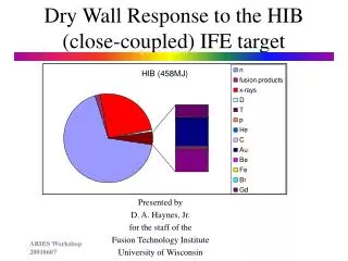
Chamber Physics Needs to be Understood • Dynamics of chamber gas (including fusion micro-explosion products) need to be understood to ascertain chamber conditions prior to each shot (UCSD model) - Multi-dimensional - Heat transfer mechanisms (including radiation) - Turbulence effects - Laser lines and effect on final optics - Impact target injection and survival Chamber Gas Ion and Photon Attenuation for Chamber with R=6.5 m (from BUCKY) Example temperature distribution in chamber from SPARTAN analysis Ion and Photon Threat Spectra and Chamber Conditions Prior to Each Shot Must Be Well Characterized (UW) • Attenuation of ion and photon spectra seen by wall by using a protective chamber gas
Must Ensure Successful Injection & Tracking and Survival of Target (GA/UCSD/LLE) • Target survival - Must accommodate heat transfer from background gas and wall radiation and meet target integrity requirements based on target physics - Possibility of designing more thermally robust target • Target injection & tracking - Gas gun or electromagnetic injection - ±5 mm target injection accuracy, ~2 mm target/laser accuracy - mirror steering synchronized with target tracking GA target injection facility
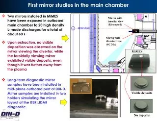
Long Term Survival & Optical Fidelity Required of Final Optics Material choices: • Monolithic Al (>99.999% purity) • Electroplating • Thin film deposition on stiff, lightweight, radiation-resistant substrate (e.g. SiC) • Surface finishing • Advanced Al alloys UCSD Laser Lab • We are developing damage-resistant final optics based on grazing-incidence metal mirrors and testing them (effort coordinated by UCSD; LLNL) Mirror requirements: - 5 J/cm2 - 2 yrs, 3x10⁸ shots - 1% spatial non-uniformity - 20 mm aiming - 1% beam balance
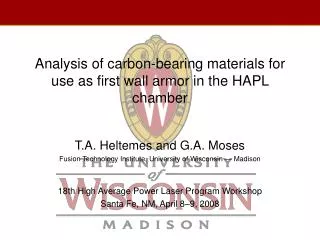
Credible Armor/First Wall Configuration to Accommodate the Threat Spectra and Provide the Required Lifetime Ions + X-rays • Exposure experiments + modeling to determine response of candidate material configuration to IFE ion and photon threats - High temperature, repetitive pulses - Thermo-mechanical response - Lifetime W FS Coolant DRAGONFIRE (UCSD Laser Lab) [mimic x-rays & ions] RHEPP (SANDIA) [repetitive ions] Z (SANDIA) [Single shot x-rays] ZAPPER -LLNL [rep-rate x-rays] • Separation of function: armor for threat accommodation; FW for structural function - Front runner configuration: thin W armor (~ 1 mm) on FS
Assessment of Potential Causes of Armor Failure and Consideration Advanced “Engineered” Material for Potentially Superior Performance • W/FS bond development (ORNL) - Testing in infrared facility (ORNL) - Modeling (T cycles, fatigue) (UW) • He retention - He implantation/anneal cycle experiment + modeling (ORNL+UNC) - He + D implantation in IEC facility (UW) • Development of engineered (porous) W armor for longer lifetime (UCLA/Ultramet, PPI/UCSD) - Stress relief - Enhanced release of implanted He ions (microstructure dimension smaller than He migration distance) Vacuum Plasma Spray Porous W (PPI/UCSD) W foam (Ultramet/UCLA)
The Blanket and Beyond: Strategy for Blanket Development and Integrated System Studies Study (UCSD/UW/LLNL) Example Ceramic Breeder Blanket Concept Example Self-Cooled Li Blanket Concept • System Studies Comprise a Multi-Step Approach: • 1. Develop tools and constraints and perform initial and scoping analysis of parameter space that accommodates material and design constraints. • 2. Complete integrated system code for laser IFE that includes performance scaling, constraints, cost for all major parts of the power plant (targets, drivers, chambers, power plant facilities, etc.) • 3. Perform full trade-off studies to help develop an integrated HAPL power plant conceptual design Example Brayton Power Cycle • Blanket strategy aims at making the most of MFE design and R&D info in developing an attractive IFE blanket concept 1. Scoping study of blanket concepts coupled to selected power cycle(s) to the point where we can intelligently evaluate them and select most attractive one(s). 2. Detailed design analysis of selected concept(s) closely integrated with our system studies and with design of interfacing components
Interfaces Among the Different Components Very Important in Developing an Integrated View of an HAPL Power Plant • Phase I effort focused on basic science and technology of different components • Effort has started to evolve a consistent integrated concept for an HAPL power plant based on the initial results available for the various components. - Concept will evolve as R&D and analysis progress. - Help highlight interface issues that need to be addressed - Help build credible case to go to Phase II. Initial Effort on Evolving In-Vessel Machine Layout
Example Integration Analysis of Chamber Armor/FW/Blanket (including Interface with Target Survival) Start with spectra from NRL 154 MJ direct-drive target - Photon • Fast ions • Debris ions
W FS Coolant q Calculate Energy Deposition in Armor Based on Spectra and Time of Flight Effect • Use results of photon and ion energy deposition analysis as input in RACLETTE-IFE code to calculate cyclic armor thermal response
q W FS Coolant (h) Example Results Comparing W Temperature Histories for Armor Thicknesses of 0.05 mm and 0.5 mm, respectively dW=0.05mm dW=0.5mm 154 MJ yield No gas Rep Rate =10 Rchamber = 6.5 m dFS = 2.5mm Tcoolant= 500°C • Not much difference in maximum W temperature and in number of cycles to ramp up to the maximum temperature level
Example Results Comparing FS Temperature Histories for W Armor Thicknesses of 0.05 mm and 0.5 mm, Respectively dW=0.05mm dW=0.5mm • Substantial differences in max. TFS and cyclic DTFS at FS/W interface depending on dW • Can adjust Tmax by varying Tcoolant and hcoolant • Design for separate function and operating regime: - armor function under cyclic temperature conditions - structural material, coolant and blanket operation designed for quasi steady-state 154 MJ yield No gas Rep Rate =10 Rchamber = 6.5 m dFS = 2.5mm Tcoolant= 500°C
Maximum TW, TFS, DTFS as a Function of Armor Thickness for Example Parameters • Maximum W temperature is virtually constant over range of armor thicknesses, ~ 3050°C • Must be integrated with chamber system modeling for consistent overall blanket and armor design parameters • For given IFE conditions and chamber parameters, set maximum possible dW (to minimize cyclic DTFS and FS Tmax and provide lifetime margin) that would accommodate: - maximum allowable TW - fabrication
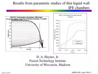
Procedure for Example Parametric Armor Analysis • Utilize consistent parameters from steady state parametric study of example blanket/FW/power cycle configuration (FS/Li/Brayton Cycle) - Maximum coolant temperature in FW ~ 572°C • 1-mm W armor over 3.5-mm FS assumed for analysis - maintain cyclic DTFS <~20° C for example cases - also applicable for higher energy density cases as increasing the W thickness in the range of ~1 mm has only a ~10°C effect on the max. TW - could be regarded as a mid-life or end of life scenario also • For given fusion power from blanket analysis, calculate combination of yield, chamber radius and protective gas density which would maintain assumed maximum W armor temperature limit - Not clear which chamber gas (if any) to use; Xe assumed for example case - Gas attenuation estimated from BUCKY results with different chamber gas density - Reduction in photon/burn ion/debris ion of 9%/1%/29% for 10mtorr Xe and R=6.5 m - Reduction of 16%/2%/48% for 20mtorr Xe and R=6.5 m - Conservative assumption: shift ion energy spectrum correspondingly - Heat in gas reradiated to surface over time 300-700 ms
Example Results of Armor Parametric Analysis Illustrating Combination of Xe Chamber Pressure, Yield and Chamber Size to Maintain W Armor Within 2400°C for a Fusion Power of 1800 MW Example target survival constraints based on allowable q’’ (including 0.25 W/cm2 radiation from wall) to reach DT triple point for assumed 16 K, 400 m/s target and 4000 K Xe in chamber: • Baseline target • Insulated target (with 100mm 10% dense foam) • W temperature limit of 2400°C assumed for illustration purposes • Actual limit based results of ongoing experimental and modeling armor R&D effort • Other requirements such as pumping need to be considered when setting chamber gas and pressure
Conclusions • The HAPL Program Aims at Developing a New Energy Source: IFE Based on Lasers, Direct Drive Targets and Solid Wall Chambers • The Path to Develop Laser Fusion Energy Envisions 3 Phases - Basic fusion science & technology - Validate science & technology - Engineering test facility • HAPL Phase I Effort Proceeding Well - R&D on specific components focused on solving major issues - Interfaces and requirements among components/systems - Integrated view to develop consistent parameters for the core of a laser IFE power plant