Download
1 / 54
600 likes | 757 Vues
Explore the basic concepts of magnetic spectrometers and mass separators, covering principles of charged particles in magnetic fields, dipole and quadrupole magnets, and mass separation techniques. Learn about PRISMA, SPEG, LISE, FRS, and more.

E N D
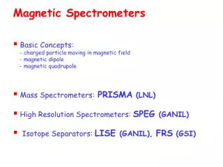
Magnetic Spectrometers • Basic Concepts: - charged particle moving in magnetic field - magnetic dipole - magnetic quadrupole • Mass Spectrometers:PRISMA (LNL) • High Resolution Spectrometers: SPEG (GANIL) • Isotope Separators: LISE (GANIL), FRS (GSI)
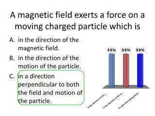
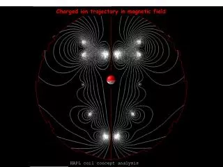
Magnetic Rigidity Dipole Magnet Charged particle moving in Uniform Magnetic Field a dipole with a uniform dipolar field deviates a particle by an angle q B direction into plane magnetic force changes only v direction ( v = v0 ; F is centripetal force) curvature radius q depends on length L and field B: if q is small: Br is called magnetic rigidity: momentum using correct units: Br = 33.356 p [kG m ] = 3.3356 p [T m](if p is in [GeV/c])
a dipole magnet is the ion-optical equivalent of a prism - a dipole introduces dispersion at any position s [a relation between momentum and position] - dispersion function D(s) can be calculated: it has the unit of meters - beam has a finite horizontal size (due to momentum p spread) - normally NO vertical dipoles D(s) =0 in vertical plane Dipole Selection local radial displacement due to momentum spread dispersion function
Examples of Magnetic Dipole Large acceptance (angle & momentum) Limited acceptance (angle & momentum) ALADIN (GSI) ALarge Acceptance DIpole magNet FRS (GSI) FRagment Separator magnetic selection in A, Z, v: only particles with a limited range of bending radii, centered around 0, can pass. [N.B. 0 is defined by the geometry of the magnet] for particle velocity evaluation obtained from measurement of particle trajectory already knowm from independent measurement Dipoles, constrain the beam to some closed path (orbit)
magnetic field Quadrupole Magnet focusing of the beam a quadrupole magnet has 4 poles: - 2 north and 2 south - simmetrically arranged around the centre of the magnet - No magnetic field along the central axis on the x-axis (horizontal) the field is vertical and given by: hyperbolic contour x·y = constant By x on the y-axis (vertical) the field is horizontal and given by: Field gradientK Bx y
Types of Magnetic Quadrupoles Focusing Quadrupole (QF) Defocusing Quadrupole (QD) it focuses the beam horizontally and defocuses the beam vertically rotating the QF magnet by 90° will give verticalfocusing and horizontal defocusing forces on particles pair of quadrupoles with a drift section in between is the ion-optical equivalent of a lens. Focusing and Defocusing Quadrupoles provide horizontal and vertical focusing in order to constrain the beam in transverse directions
The mechanical equivalent illustration of how particles behave due to the quadrupolar fields whenever a beam particle diverges too far away from the central orbit the quadrupoles focus them back towards the central orbit
p > p0 p < p0 Other focusing magnets Sextupoles: correction of chromaticity introduced by quadrupoles focusing quadrupole in horizontal plane particles with higher momentum are deviatedless in the quadrupole QF p0 particles with lower momentum will be deviated more in the quadrupole
x’ emittance beam x acceptance Beam Emittance & Acceptance • observe all the beam particles at a single position • measure both position and angle • this gives a large number of points in our phase space plot: • each point represents a particle with co-ordinates x,x’ emittance = area of the ellipse, which contains all, or a defined percentage, of the particles. acceptance = maximum area of the ellipse, which the emittance can attain without losing particles
Magnetic MASS Spectrometers Physics Aim: attribution of a reaction product to a nucleus high efficiency over a wide range of masses and energies Examples: ▪binary reactions 5-10 MeV/A: elastic, inelastic and multinucleon transfer population of moderately n-rich nuclei PRISMA @ LNL, BRS @ EUROBALL ▪radioactive beams: simultaneus population of many nuclei wide range of masses, energies, scattering angles PRISMA @ LNL(Spes), VAMOS @ GANIL (Spiral) ▪fusion evaporation reactions: Gas Filled Mode operation high efficiency and 0° operation RITU @ JYFL, PRISMA @LNL need for spectrometer with: -large solid angle (up to 100 msr) - large p acceptance ( 10%) - good mass resolution (via TOF)
PRISMA (LNL) Large Acceptance Spectrometer for Heavy Ions (A=100-200, E=5-10MeV/A) Study of multinucleon transfer reactions populating moderately n-rich nuclei Optical elements PRISMA Detectors 1.Quadrupole (QF) a singlet vertical focus of ions towards dispersion plane 1.Entrance Detector MCP entrance position xs - ys, time 2.Focal Plane Detector PPAC xf - yf, time 2.Dipole horizontal bending of ions according to their magnetic rigidity (Br) 3.Ionization Chamber energy loss, total energy physical event (xs, ys, xf, yf, TOF, ∆E, E)
(Br)max A.M. Stefanini et al., NIMA701(2992)217c F. Scarlassara et al., NPA746(2004)195c
Mounting of the DIPOLE DIPOLE & QUADRUPOLE dipole field region under vacuum
glass structure • Microchannel plates • compact electron multipliers of high gain • G 106-108 • used in wide range of • particle and photon detection systems • 107 closely packed channels of common diameter • (formed by drawing, etching, or firing • in hydrogen, a lead glass matrix) • typical channel diameter D10 mm • - each channel acts as • an independent, continuous dinode photomultiplier • - gain G increases withL/D(typically 75:1 – 175:1) channel • performances • efficiency • not more than 60% for X-rays • higher for charged particles • time-resolution • ultra-high: < 100 ps • spatial resolution • (limited by channel dimensions & spacing): 12-15 mm • relative immunity to magnetic fields: • single MCP:completely unaffected in B 0.5 Tesla • in stack: completely unaffectd by much higher fields efficiency J. L. Wiza, NIMA162(1979)587
Entrance Position Detector(Multi Channel Plate) • active area: 8x10 cm2 (Ω=80msr) • full coverage of PRISMA spectrometer • at d = 25cm from target • timing resolution for TOF ~ 350 ps • C foil: 20mg/cm2 thick • Eacc = 30-40 kV/m • parallel magnetic field: B120 Gauss • to limit the spread of electron cloud • preserving particle position infformation 2 orthogonal delay lines 70 mm Cu-Be wires vacuum case a-particle irradiation from 241Am holes: =1 mm D=5 mm Target C-foil FWHM=1.1 mm mask in front MCP Ion beam 3 signals: x, y, time Q-pole
Multi Channel Plate coil position sensitive anode G. Montagnoli et al., NIMA547(2005)455
Focal Plane Detectors: Multi WirePPAC • - active area: 1m x 13 cm - 3 electrode structure: central cathod & 2 anodic wire planes (X and Y) - cathode: 3300 wires of 20mm gold-plated tungsten 0.3 mm spacing 10 independent sections of 10x13 cm2 negative high voltage: 500-600 V • -X plane: 10 sections of 100 wires each, 1mm spacing • - Y plane: common to all cathode, • 130 wires, 1 m long, 1mm steps - spatial resolution: ∆X ~ 1mm, ∆Y ~ 2mm (FWHM) - stop signal for TOF 2.4 mm to ionization chambers mylar foils 1.5 mm entrance window mylar foils 1.5 mm 3 electrode structure: 1000 wires Filling gas: C4H10 Filling pressure: 7 mbar delay-line readout 10 x 3 signals (Xl, Xr, timing) 2 signals (Yu, Yd)
ePPAC~90% 92 MeV 24Mg+24Mg 28Si 24Mg 25Mg 20Ne 122 MeV 32S+58Ni 21Ne 19Ne 16O 12C ePPAC~60-70% 13C E. Fioretto INFN - LNL FPD efficiency for light-ions Mass region : A=12-32
Focal Plane Detectors: Ionization Chamber - 10x4 sections (10x25 cm2) - depth: 120 cm - ∆E/E < 2% - anode & cathode:10x4 sections - Frisch grid: 1000 wires, 100 mm diameter 1 mm spacing, 1 m long 10x4 sections Filling gas: CH4, 99% purity (CF4 for energetic heavy-ions) Filling pressure: 20-100 mbar cathode 100 cm anode 40x2 signals
Ionization Chamber pulse mode operation with Frisch grid The fine mashing grid removes the pulse-amplitude dependence on position of interaction Frisch d = 1.6 cm in PRISMA Ionization Chamber d = 16 cm
Tandem(GF)-ALPI PIAVE-ALPI C4H10 CF4 CH4 Emax (AMeV) 16O 56Fe 35Cl 80Se 40Ca 132Xe Maximum energy stopped into the IC CF4 Si 100 hPa~168 mm 14 AMeV ≤ Emax ≤ 16 AMeV CH4 Si 100 hPa ~59 mm Emax~ 6 AMeV Atomic Number 160 MeV 16O+186W PRISMA @ 40°<q>~8 154 MeV 16O ions 110 hPa BDipole~ 68% - BQuadrupole~ 60% E. Fioretto INFN - LNL
Focal Plane Detectors: in-beam tests IC MWPPAC (e~ 100%) 195 MeV 36S + 208Pb, Θlab = 80o dispersion in X (DIPOLE) Z=28 E (a.u.) Z=16 X position (channels) 240 MeV 56Fe+124Sn, Θlab = 70° Z=26 different shapes due to PRISMA optics ∆t ~ 300 ps ∆X = 1 mm ∆Y = 2 mm E (a.u.) focusing in Y (QUADRUPOLE) ∆E/E < 2% ΔZ/Z ~ 60 Y position (channels) E (a.u.)
Mass & Energy reconstruction with PRISMA: via TOF M = qB r/v v = S(q)/TOF DA/A=1/280 • Optical elements + TOF • Energy loss in IC + residual energy after ion-tracking reconstruction B r = p/q M/q = (Br TOF)/S(q) 505 MeV 90Zr+208Pb exact identification of mass (A) and charge (Z) + distinction of charge states (Q)
CLARA-PRISMA setup Quadrupole Dipole Start detector X-Y, time IC 6m (TOF) E-ΔE MWPPAC Angular range 30o - +130o X-Y, time ΔΩ = 80 msr ΔZ/Z 1/60 (Measured) ΔA/A 1/190 (Measured) Energy acceptance ±20% Bρ = 1.2 T.m PRISMA: Large acceptance Magnetic Spectrometer A. Gadea et al., EPJA20(2004)193
CLARA-PRISMA setup PRISMA A & Z identification “in-beam” γ-ray CLARA 25 Euroball Clover detectors Efficiency~3 %::Eγ= 1.3MeV
Future Development: PRISMA in Gas Filled Mode Physics Aim: measurements of evaporation residues with small s, recoiling at 0° need for high transmission efficiency • Main drawback:loss of mass & energy resolution • the magnetic spectrometer is used as a separator Existing devices: RITU (JYFL), TASCA (GSI), … for heavy element study (s < 1nb) M. Leino et al., NIMB99(1995)653 T. Back et al., EPJA16(2003)489
Principle of operation gas vacuum high transmission efficiency can be obtained filling the dipole region with a dilutedgas q <q> q+1 q+2 q+3 - collision between reaction products and gas atoms lead to charge state focusing - trajectory determined by average ionic charge - Br does NOT depend on v energies merge !!! - it can be used to get a rough estimate of degree of separation between target-like products fusion evaporation residues example: 40Ar + 175Lu 210,211Ac + xn v0 = 2.19 106 m/s Bohr velocity qave= (v/v0) Z1/3 Thomas-Fermi model
Focal Plane position spectra for 58Ni at 350 MeV • typical GFM pressure: 1 mbar = 0.75028 Torr • typical gas: H, He M. Paul et al., NIMA277(1989)418
Magnetic Rigidity Limits NOT central trajectory (30 cm shift from center) Br= 1.5 MeV limitation to A 200 PRISMA central trajectory Br 1.2 MeV limitation to A < 180
using NOT central trajectories one can focus on larger Br heavier ions 40% efficiency to separate reaction products
to implant reaction products and to measure subsequent a, b or p emission - good energy resolution - high efficiency - good spatial resolution 3 mm
Focal Plane Detectors of RITU (JYFL) GREAT Array: decay tagging technique • 1.Double Sided Silicon Strip Detectors: • implantation of reaction products • and measure of subsequent a, b or p emission • 2.Si PIN photodiode: • measure of conversion electron energies • 3.Double Sided Ge Strip Detectors: • measure of X-rays, low-energy g and b-particles • 4.High efficiency CLOVER Ge: • measure of high-energy g-rays • 5.MWPAC: • active recoil & beam discriminator • [also used for rejection of decay particles leaving • only partial energy in Si and Ge detectors] R. Page et al., NIMB204(2003)634
Magnetic High Resolution Spectrometers • Physics Aim: high resolution energy/momentum measurements • DE/E 10-5 Dp/p 10-4 • Example: • - beam energy up to 100 MeV/A • few 100 keV energy resolution • angular distribution with strong forward focusing • for A = 100, 100MeV/A DE/E 10-5 Dp/p 10-4 • Dp/pbetter than beam momentum resolution Dp/p 510-3 • Dp/pachievable via TOF withlong flight paths DL/L 10-5 L 100 m • need for high resolution spectrometer
Study of discrete nuclear states populated in reactions induced by nuclei up to 100 MeV/A beam SPEG (GANIL) Energy Loss High Resolution Spectrometer achromatic device (i.e final position & angle do not depend on momentum) • analysing beam line • energy loss spectrometer dispersion on target 9.86 m mean bending radius 3 m mean deflection angle 75° maximum dipole B 1 T • Dp/p 510-3 • emittance 5p mm mrad • object size 4x4 mm2 E, DE nominal dispersion 8.1 m solid angle 4.9 msr mean bending radius 2.4 m mean deflecting angle 2x42.5=85° maximum B in Dipoles 1.2 T analyzed momentum range 7% length of focal plane 60 cm angular range -10° to +105° • Dp ~ 10-4 (from 2 positions measurements) ion identification: A from TOF Z from DE-E Si telescopes 1.3-1.6 % and 0.8-1.1 % resolution
SPEG analyzing magnet DA 1 spectrometer dipoles D1 & D2 2 L. Bianchi et al., NOMA276(193)509 determination of magnetic rigidity d of each ions flight path L = 82m two horizontal position sensitive measurements: 1. MCP at dispersive plane of analyzing magnet [where dispersion in momentum is large: 10cm/%] 2. two drift chambers after spectrometers [Dx 0.6 mm, Dy 0.5 mm] dW = 4.9 msr Br = 2.9 Tm • each ion trajectory is recontructed • accurate determination of d independently of object size Dp 10-4 particle identification
identification of ions arriving at SPEG focal plane Identification matrix Telescope of 4 cooled silicon detectors 50 mm 300 mm 6000 mm 6000 mm (anti-coincidence) • energy loss • total energy • time of flight • isomer g-decay: NaI detectors Aidentification long flight path L = 82 m time of flight Tvol = 700 ns-1.2 ms mass resolutionDm/m 10-4
mass resolution: 3 MeV of mass excess Sarazin et a., PRL84(2000)5062
Magnetic Separators • Physics Aim: ??? • Example: • - Radioactive beam ??? • need for ???
LISE: achromatic spectrometer Achromatic spectrometer: position and angle of the ion at the end of the Device (focal plane) DO NOT depend on the ion’s momentum. OBJECTIVES: The LISE device has 2 principle objectives: 1) To produce and select radioactive nuclei 2) To produce and select highly stripped ions (with few electrons) METHOD OF PRODUCTION OF RADIOACTIVE NUCLEI: The production of radioactive nuclei is carried out using stable nuclei, accelerated by the GANIL accelerator, and projected towards a fixed target which has a thickness of the order of millimetres, eg carbon. (see figure 1).