
River Model of Electric Circuits: Understanding Series Circuits
E N D
Presentation Transcript
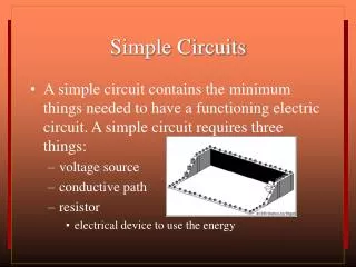
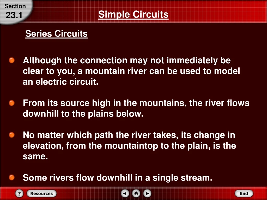
Section Simple Circuits 23.1 Series Circuits • Although the connection may not immediately be clear to you, a mountain river can be used to model an electric circuit. • From its source high in the mountains, the river flows downhill to the plains below. • No matter which path the river takes, its change in elevation, from the mountaintop to the plain, is the same. • Some rivers flow downhill in a single stream.
Section Simple Circuits 23.1 Series Circuits • Other rivers may split into two or more smaller streams as they flow over a waterfall or through a series of rapids. • In this case, part of the river follows one path, while other parts of the river follow different paths. • No matter how many paths the river takes, however, the total amount of water flowing down the mountain remains unchanged. • In other words, the amount of water flowing downhill is not affected by the path it takes.
Section Simple Circuits 23.1 Series Circuits • How does the river shown in the figure model an electric circuit? • The distance that the river drops is similar to the potential difference in a circuit. • The amount of water flowing in the river is similar to current in a circuit. • Narrow rapids create resistance and are similar to resistors in a circuit.
Section Simple Circuits 23.1 Series Circuits • What part of a river is similar to a battery or a generator in an electric circuit? • The energy source needed to raise water to the top of the mountain is the Sun. • Solar energy evaporates water from lakes and seas leading to the formation of clouds that release rain or snow that falls on the mountaintops. • Continue to think about the mountain river model as you read about the current in electric circuits.
Section Simple Circuits 23.1 Series Circuits • Three students are connecting two identical lamps to a battery, as illustrated in the figure. • Before they make the final connection to the battery, their teacher asks them to predict the brightness of the two lamps.
Section Simple Circuits 23.1 Series Circuits • Each student knows that the brightness of a lamp depends on the current through it. • The first student predicts that only the lamp close to the positive (+) terminal of the battery will light because all the current will be used up as thermal and light energy. • The second student predicts that only part of the current will be used up, and the second lamp will glow, but more brightly than the first. E = Pt
Section Simple Circuits 23.1 Series Circuits • Each student knows that the brightness of a lamp depends on the current through it. • The third student predicts that the lamps will be of equal brightness because current is a flow of charge and the charge leaving the first lamp has nowhere else to go in the circuit except through the second lamp. • The third student reasons that because the current will be the same in each lamp, the brightness also will be the same. • How do you predict the lights will behave?
Section Simple Circuits 23.1 Series Circuits • If you consider the mountain river model for this circuit, you will realize that the third student is correct. • Recall that charge cannot be created or destroyed. Because the charge in the circuit has only one path to follow and cannot be destroyed, the same amount of charge that enters the circuit must leave the circuit. • This means that the current is the same everywhere in the circuit.
Section Simple Circuits 23.1 Series Circuits • If you connect three ammeters in the circuit, as shown in the figure, they all will show the same current. • A circuit in which all current travels through each device, is called a series circuit.
Equivalent Resistance for Resistors in Series R = RA + RB + … Section Simple Circuits 23.1 Current and Resistance in a Series Circuits • For resistors in series, the equivalent resistance is the sum of all the individual resistances, as expressed by the following equation. • Notice that the equivalent resistance is greater than that of any individual resistor. • Therefore, if the battery voltage does not change, adding more devices in series always decreases the current.
Current Section Simple Circuits 23.1 Current and Resistance in a Series Circuits • To find the current through a series circuit, first calculate the equivalent resistance and then use the following equation. • Current in a series circuit is equal to the potential difference of the source divided by the equivalent resistance.
Section Simple Circuits 23.1 Voltage Drops in a Series Circuit Two resistors, 47.0 Ω and 82.0 Ω, are connected in series across a 45.0-V battery. • What is the current in the circuit? • What is the voltage drop across each resistor? • If the 47.0-Ω resistor is replaced by a 39.0-Ω resistor, will the current increase, decrease, or remain the same? • What is the new voltage drop across the 82.0-Ω resistor?
Section Simple Circuits 23.1 Voltage Drops in a Series Circuit Draw a schematic of the circuit.
Section Simple Circuits 23.1 Voltage Drops in a Series Circuit Identify the known and unknown variables. Known: Vsource = 45.0 V RA = 47.0 Ω RB = 82.0 Ω Unknown: I = ? VA = ? VB = ?
and R = RA + RB Section Simple Circuits 23.1 Voltage Drops in a Series Circuit • To determine the current, first find the equivalent resistance.
Section Simple Circuits 23.1 Voltage Drops in a Series Circuit Substitute R = RA + RB Substitute Vsource = 45.0 V, RA = 47.0 Ω,RB = 82.0 Ω = 0.349 A
Section Simple Circuits 23.1 Voltage Drops in a Series Circuit • Use V = IR for each resistor. VA = IRA Substitute I = 0.349 A, RA = 47.0 Ω VA= (0.349 A)(47.0 Ω) = 16.4 V
Section Simple Circuits 23.1 Voltage Drops in a Series Circuit VB = IRB Substitute I = 0.349 A, RA = 82.0 Ω VB = (0.349 A)(82.0 Ω) = 28.6 V
Section Simple Circuits 23.1 • Calculate current, this time using 39.0 Ω as RA. Substitute Vsource = 45.0 V, RA = 39.0 Ω,RB = 82.0 Ω = 0.372 A The current will increase.
Section Simple Circuits 23.1 Voltage Drops in a Series Circuit • Determine the new voltage drop in RB. VB = IRB Substitute I = 0.372 A, RA = 82.0 Ω VB = (0.372 A)(82.0 Ω) = 30.5 V
Section Simple Circuits 23.1 Parallel Circuits • How many current paths are there?
Section Simple Circuits 23.1 Parallel Circuits • The current from the generator can go through any of the three resistors. • A circuit in which there are several current paths is called a parallel circuit. • The three resistors are connected in parallel; both ends of the three paths are connected together. • In the mountain river model, such a circuit is illustrated by three paths for the water over a waterfall.
Section Simple Circuits 23.1 Parallel Circuits • Some paths might have a large flow of water, while others might have a small flow. • The sum of the flows, however, is equal to the total flow of water over the falls. • In addition, regardless of which channel the water flows through, the drop in height is the same. • Similarly, in a parallel electric circuit, the total current is the sum of the currents through each path, and the potential difference across each path is the same.
Section Simple Circuits 23.1 Series Circuits • What is the current through each resistor in a parallel electric circuit? • It depends upon the individual resistances. • For example, in the figure, the potential difference across each resistor is 120 V.
Section Simple Circuits 23.1 Series Circuits • The current through a resistor is given by I = V/R, so you can calculate the current through the 24-Ω resistor as I = (120 V)/(24 Ω) = 5.0 A and then calculate the currents through the other two resistors. • The total current through the generator is the sum of the currents through the three paths, in this case, 38 A.
Section Simple Circuits 23.1 Series Circuits • What would happen if the 6-Ω resistor were removed from the circuit? • Would the current through the 24-Ω resistor change? • The current depends only upon the potential difference across it and its resistance; because neither has changed, the current also is unchanged.
Section Simple Circuits 23.1 Parallel Circuits • The same is true for the current through the 9-Ω resistor. • The branches of a parallel circuit are independent of each other. • The total current through the generator, however, would change. • The sum of the currents in the branches would be 18 A if the 6-Ω resistor were removed.
Section Simple Circuits 23.1 Resistance in a Parallel Circuit • How can you find the equivalent resistance of a parallel circuit? • In the figure shown, the total current through the generator is 38 A.
Section Simple Circuits 23.1 Resistance in a Parallel Circuit • Thus, the value of a single resistor that results in a 38-A current when a 120-V potential difference is placed across it can easily be calculated by using the following equation: = 3.2 Ω
Section Simple Circuits 23.1 Resistance in a Parallel Circuit • Notice that this resistance is smaller than that of any of the three resistors in parallel. • Placing two or more resistors in parallel always decreases the equivalent resistance of a circuit. • The resistance decreases because each new resistor provides an additional path for current, thereby increasing the total current while the potential difference remains unchanged.
Section Simple Circuits 23.1 Resistance in a Parallel Circuit • To calculate the equivalent resistance of a parallel circuit, first note that the total current is the sum of the currents through the branches. • If IA, IB, and IC are the currents through the branches and I is the total current, then I = IA + IB + IC. • The potential difference across each resistor is the same, so the current through each resistor, for example, RA, can be found from IA = V/RA.
Equivalent Resistance for Resistors in Parallel Section Simple Circuits 23.1 Resistance in a Parallel Circuit • Therefore, the equation for the sum of the currents is as follows: • Dividing both sides of the equation by V provides an equation for the equivalent resistance of the three parallel resistors. • The reciprocal of the equivalent resistance is equal to the sum of the reciprocals of the individual resistances.
Section Simple Circuits 23.1 Resistance in a Parallel Circuit • Series and parallel connections differ in how they affect a lighting circuit. • Imagine a 60-W and a 100-W bulb are used in a lighting circuit. Recall that the brightness of a lightbulb is proportional to the power it dissipates, and that P = I2R. • When the bulbs are connected in parallel, each is connected across 120 V and the 100-W bulb glows more brightly.
Section Simple Circuits 23.1 Resistance in a Parallel Circuit • When connected in series, the current through each bulb is the same. • Because the resistance of the 60-W bulb is greater than that of the 100-W bulb, the higher-resistance 60-W bulb dissipates more power and glows more brightly.
Section Section Check 23.1 Question 1 What is a series circuit? How is it different from a parallel circuit?
Section Section Check 23.1 Answer 1 A circuit in which all the current travel through each device is called a series circuit. A series circuit can be understood with the help of the following circuit diagram. In the above circuit, the current through all the three resistances, RA, RB, and RC, is the same even though the resistances are different. The current through the circuit can be determined by using ohm’s law, that is, I = V/R, where R is the equivalent resistance of the circuit.
Section Section Check 23.1 Answer 1 In the above circuit the current flowing through each device (resistances RA, RB and RC) is,
Section Section Check 23.1 Answer 1 On the other hand, a circuit in which there are several current paths as shown in the following figure, is called a parallel circuit. In a parallel circuit, the total current is the sum of the currents through each path. In case of the above circuit, I = I1 + I2 + I3
Section Section Check 23.1 Answer 1 Contrary to a series circuit, in a parallel circuit, the potential difference across each path is the same. In the above figure, the potential difference across each resistance RA, RB, and RC is equal to 15 V. That is, V = VA = VB = VC = 15 V.
Section Section Check 23.1 Question 2 Three resistors of resistance 2 Ω each are connected in series with a battery. What is the equivalent resistance of the circuit? • 2 Ω • 6 Ω
Section Section Check 23.1 Answer 2 Answer: B Reason: Equivalent resistance for resistors in series is given by, R = RA + RB + . . . The equivalent resistance of resistors in series is equal to the sum of the individual resistances of the resistors. In this case, R = 2 Ω+ 2 Ω + 2 Ω = 6 Ω
Section Section Check 23.1 Question 3 What will be the ammeter reading in the following circuit? • (10 Ω)(12 V)
That is, Section Section Check 23.1 Answer 3 Answer: B Reason: The given circuit is a series circuit and the current through a series circuit is constant. Current in a series circuit is equal to the potential difference of the sources divided by the equivalent resistance. In this case, Vsource = 12 V and equivalent resistanceR = 10 Ω + 10 Ω.
Section Section Check 23.1 Answer 3 Reason: In this case, Vsource = 12 V and equivalent resistanceR = 10 Ω + 10 Ω.
Section Section Check 23.1 Question 4 What is the voltmeter reading in the following circuit?
Section Section Check 23.1 Answer 4 Answer: B Reason: The given circuit is a potential divider circuit. A voltage divider is a series circuit used to produce a voltage source of desired magnitude from a higher voltage battery. To calculate the voltage across RB (10-Ω resistor), we first calculate the current flowing through the circuit. That is,
Section Section Check 23.1 Answer 4 Reason: We need to calculate the voltage VB (Voltage across RB). Using ohm’s law, we can write, VB = IRB. Substituting the value of I from the above equation, we get,
Section Applications of Circuits 23.2 Combined Series-Parallel Circuits • Have you ever noticed the light in your bathroom or bedroom dim when you turned on a hair dryer? • The light and the hair dryer are connected in parallel across 120 V. • Because of the parallel connection, the current through the light should not have changed when you turned on the hair dryer. • Yet the light did dim, so the current must have changed. • The dimming occurred because the house wiring had a small resistance.
Section Applications of Circuits 23.2 Combined Series-Parallel Circuits • As shown in the figure, this resistance was in series with the parallel circuit. • A circuit, which includes series and parallel branches, is called a combination series-parallel circuit.
Section Applications of Circuits 23.2 Series-Parallel Circuit A hair dryer with a resistance of 12.0 Ω and a lamp with a resistance of 125 Ω are connected in parallel to a 125-V source through a 1.50- Ω resistor in series. Find the current through the lamp when the hair dryer is on.