Download
1 / 27
270 likes | 371 Vues
Explore the physics design of NDCX-II for ion beam-driven studies, focusing on warm dense matter and ion direct drive. Key components, technologies, and cost estimates are discussed, highlighting the machine's upgrade over NDCX-I. The text provides insights into beam acceleration, focusing, velocity tilt, and waveform generation for experiments. Considerations for beam compression, space charge effects, and velocity control principles are detailed, emphasizing the innovative design approach used in NDCX-II.

E N D
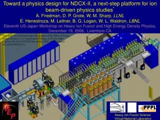
Toward a physics design for NDCX-II, a next-step platform for ion beam-driven physics studies*A. Friedman, D. P. Grote, W. M. Sharp, LLNLE. Henestroza, M. Leitner, B. G. Logan, W. L. Waldron, LBNLEleventh US-Japan Workshop on Heavy Ion Fusion and High Energy Density Physics, December 19, 2008, Livermore CA *This work was performed under the auspices of the Office of Fusion Energy Sciences, U.S. Department of Energy, by LLNL under Contract DE-AC52-07NA27344, and by LBNL under Contract DE-AC02-05CH11231. Heavy Ion Fusion Science Virtual National Laboratory
For Warm Dense Matter studies, the NDCX-II beam must be accelerated to 3-4 MeV and compressed to ~1 ns (~1 cm) THIN TARGET Exiting beam available for dE/dx measurement LITHIUM ION BEAM BUNCH Final Beam Energy:3-4 MeV Final Spot Size : ~ 1 mm diameter Total Charge Delivered: 30 nC (~ 2x10¹¹ particles or Imax ~ 30 A)
NDCX-II will enable studies of warm dense matter and key physics for ion direct drive
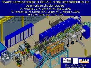
At least 40 ATA cells are available for NDCX-II water-filled Blumleins 100mA, 500ns Li+ ion injector oil-filled transmission lines 30 ATA induction cells with pulsed 1-3T solenoids final energy correction induction cell neutralized drift compression region with plasma sources final focus and target chamber with diagnostics Estimated cost: $6M (includes contingency)
NDCX-II represents a significant upgrade over NDCX-I • Baseline for WDM experiments: 1-ns Li+ pulse (~ 2x10¹¹ ions, 30 nC, 30 A) • For experiments relevant to ion direct drive: require a longer pulse with a “ramped” kinetic energy, or a double pulse.
solenoid water cooling Test stand allows us to study cells in detail ATA cells are in good condition and match NDCX-II needs well • They provide short, high-voltage accelerating pulses: • Ferrite core: 1.4 x 10⁻³ Volt-seconds • Blumlein: 200-250 kV for 70 ns • At front end, longer pulses need custom voltage sources; < 100 kV for cost Cells will be refurbished with stronger, pulsed solenoids
NDCX-II uses an accel-decel injector in which the “einzel lens” effect provides transverse confinement ground +102 kV pulsed source +68 kV DC -170 kV DC solenoid 10 mA/cm2 extraction electrode accel electrode
Some issues were resolved; favorable features emerged Issues: • An accelerating gap must be “on” while any of the beam overlaps its extended fringe field • To shorten the fringe, the 6.7-cm radius of the ATA beam pipe is reduced to 4.0 cm • Some pulses must be “shaped” to combat space charge forces • We’ll do this via inexpensive passive circuits • Space is limited • 30-cell design (20 Blumleins + 10 lower-voltage sources) fits easily Favorable features: • Most of machine uses modular 5-cell “blocks” • Induction cells can impart all or most of final ~8% velocity “tilt” • Current of compressed beam varies weakly w/ target plane over ~40 cm
A simple passive circuit can generate a wide variety of waveforms Waveforms generated for various component values: charged line ATA “compen-sation box” induction cell & accelerating gap impedance
We are well on our way toward a physics design for NDCX-II • Accel-decel injector produces a ~ 100 keV Li+ beam with ~ 67 mA flat-top • Induction accelerates it to 3.5 MeV at 2 A • The 500 ns beam is compressed to ~ 1 ns in just ~ 14 m From 1-D code: 0.4 2.0 at focus entering linac 4 (C/m) (C/m) 0.1 Ek (MeV) Ek (MeV) 0.0 0.0 0.0 0 0.5 1.0 13.5 14.0 z (m) z (m)
Physics design effort relies on PIC codes • 1-D PIC code that follows (z,vz) • Poisson equation with transverse falloff (“HINJ model”) for space charge • g0 = 2 log (rpipe / rbeam0) k2 = 4 / (g0 rbeam02) • A few hundred particles • Models gaps as extended fringing field (Ed Lee’s expression) • Flat-top initial beam with parabolic ends, with parameters from a Warp run • “Realistic” waveforms: flat-top,“triangles” from circuit equation, and low-voltage shaped “ears” at front end • Interactive (Python language) • Warp • 3-D and axisymmetric (r,z) models; (r,z) used so far • Electrostatic space charge and accelerating gap fields • Time-dependent space-charge-limited emission
Principle 1: Shorten Beam First (“non-neutral drift compression”) • Compress longitudinally before main acceleration • Want < 70 ns transit time through gap (with fringe field) as soon as possible • ==> can then use 200-kV pulses from ATA Blumleins • Compress carefully to minimize effects of space charge • Seek to achieve velocity “tilt” vz(z) ~ linear in z “right away”
Principle 2: Let It Bounce • Rapid inward motion in beam frame is required to get below 70 ns • Space charge ultimately inhibits this compression • However, so short a beam is not sustainable • Fields to control it can’t be “shaped” on that timescale • The beam “bounces” and starts to lengthen • Fortunately, the beam still takes < 70 ns because it is now moving faster • We allow it to lengthen while applying: • additional acceleration via flat pulses • confinement via ramped (“triangular”) pulses • The final few gaps apply the “exit tilt” needed for Neutralized Drift Compression
A series of snapshots shows how the (Ek,z) phase space and the line charge density evolve peak compression entering linac mid-compression Ek (MeV) (C/m) z (m) exiting expanding at focus
Video: line charge density and kinetic energy profiles vs. time
We use the Warp code to simulate the NDCX-II beam in (r,z) 500 ns 1500 ns 2500 ns 3500 ns 3835 ns 3855 ns Transverse emittance growth (phase space dilution) is minimal
Preliminary Warp (r,z) beam-on-target is encouraging; transverse dynamics and focusing optics design is still at an early stage Longitudinally: the goal is achieved; most of the beam’s 0.1 J passes through the target plane in ~1.2 ns Transversely: peak fluence of 17 J/cm2 is less than the 30 J/cm2 desired; 78% of beam falls within a 1 mm spot
1-D code (top) & Warp (bottom) results agree, with differences 1680 ns 2580 ns 2880 ns Ek (MeV) (C/m) z (m) Ek (MeV) (C/m) z (m)
We look forward to a novel and flexible research platform • The design concept is compact and attractive • It applies rapid bunch compression and acceleration • It makes maximal use of ATA induction modules and pulsed power • Beam emittance is well preserved in simulations … but considerable work remains before this is a true “physics design” • NDCX-II will be able to deliver far greater beam energy and peak power for Warm Dense Matter physics than NDCX-I • We will soon begin to develop an NDCX-II acceleration schedule that delivers a ramped-energy beam, for energy coupling and hydrodynamics studies relevant to direct-drive Heavy Ion Fusion
Progress has been encouraging; much remains to be done • Proper accounting for initial beam-end energy variation due to space charge (the 1-D run shown was initiated with a fully-formed uniform-energy beam) • Other 1-D runs used a “model” initial energy variation and an entry “ear” cell; they produced compressed beams similar to the one shown • However, that variation was not realistic; a Warp run using the 1-D-derived waveforms yielded inferior compression • Better understanding of beam-end wrap-around (causes and consequences) • A prescription for setting solenoid strengths to yield a well-matched beam • Optimized final focusing, accounting for dependence of the focal spot upon velocity tilt, focusing angle, and chromatic aberration • Assessment of time-dependent focusing to correct for chromatic effects • Development of plasma injection & control for neutralized compression & focusing (schemes other than the existing FCAPS may prove superior) • Establishment of tolerances for waveforms and alignment • Major goals remain: • a self-consistent source-through-target design, including assessment of tolerances etc., for WDM studies • a prescription for modifications offering multiple pulses, ramped energy, and/or greater total energy, for ion direct drive studies
These snapshots show how the (vz,z) phase space and the line charge density evolve (note the auto-scaling) mid- compression entering linac vz (m/s) (C/m) peak compression z (m) exiting expanding at focus 13.78 13.80 t = 3118 ns
Current and radius z = 197 cm Sub ns pulse Ohm’s law 3x10¹³ plasma 3x10¹² plasma Tilt gap 5-kV e-trap plasma Simulations of NDCX-II neutralized compression and focus suggest that a plasma of density ~ 1014 cm-3 is desirable • Idealized beam, uniform plasma, so far: • Li+, 2.8 MeV, 1.67 eV temperature • 2-cm -5 or -6.7 mrad convergence • uniform current density; = 24 mm-mrad • 0.7-A with parabolic 50-ns profile • applying ideal tilt for 30 ns of beam • ½ mm 1-ns beam has 2x1013 cm-3 density Radius (LSP runs by D. Welch; others by A. Sefkow, M. Dorf; Warp code starting to be used)
We simulate injection from Cathodic-Arc Plasma sources 1.2 ns 4.5 ns • This run corresponds to an NDCX-I configuration with 4 sources • It was made by Dave Grote using Warp in 3-D mode • LSP has been used extensively for such studies