Download
1 / 32
320 likes | 449 Vues
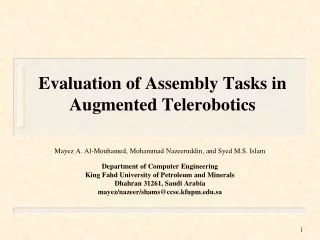
Evaluation of Assembly Tasks in Augmented Telerobotics. Mayez A. Al-Mouhamed, Mohammad Nazeeruddin, and Syed M.S. Islam Department of Computer Engineering King Fahd University of Petroleum and Minerals Dhahran 31261, Saudi Arabia mayez/nazeer/shams@ccse.kfupm.edu.sa. BACKGROUND. Background

E N D
Evaluation of Assembly Tasks in Augmented Telerobotics Mayez A. Al-Mouhamed, Mohammad Nazeeruddin, and Syed M.S. Islam Department of Computer Engineering King Fahd University of Petroleum and Minerals Dhahran 31261, Saudi Arabia mayez/nazeer/shams@ccse.kfupm.edu.sa
BACKGROUND • Background • Distributed telerobotic system • Computer Aided Telerobotics (CAT) Tools • Indexing, space scalability • Position and force tool-operator mapping • Active compliance • Teleoperation schemes • Direct teleoperation with stereo vision (V) • Direct teleoperation with stereo vision and force feedback (VFF) • Direct teleoperation with vision and active compliance (VAC) • Task specification and strategy • Insertion • Assembly • Networked teleoperation experiments • Insertion through a network • Assembly through a network • Conclusion
BACKGROUND Telerobotics: • Humans to extend their manipulative skills over a distance, • Remote manual work, .. • Real-time replication of arm motion, • Real-time 3D vision, haptic display, force, palpation, sounds, etc. Telerobotic applications • Scaled-down: nano-scale, micro-scale, surgery, etc. • Hazardous: nuclear decommissioning & inspection, disposal of dangerous objects, minefield clearance, operation in harsh environments like in space, underwater, ice, desert, .. • Safety: rescue, fire fighting,.. • Security: surveillance, reconnaissance, .. • Unmanned: oil platform inspection, repair, .. • Teaching, training, entertainment, ..
BACKGROUND CHALLENGES Extending eye-hand motion coordination through a network with high-quality perception, dexterity, and intelligent computer aided teleoperation • In natural eye-hand motion coordination, operator sees his hand and reacts accordingly. • Telerobotics: • Operator holds a master arm to dictate his hand motion, • Motion is transmitted to a remote slave arm and reproduced (replica), • Operator wears a head-mounted display (HMD) to see in 3D the effects of his motion on the remote tool, • Operator does not see his hand (HMD) nor the master arm, his hand is logically mapped to the remote tool, • Operator logically acts on the remote tool seen through the HMD. • Stereo vision: 3D perception of remote scene, a metric to calculate 3D position and orientation of objects, a tool to augment the real space (augmented reality), ..
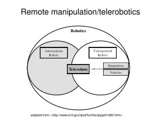
DISTRIBUTED TELEROBOTICS Client-Server distributed component telerobotic system. • A telerobotic server has components (PUMA, Force Sensor, and Decision Server) and interfaces (Proxy Robot, Sensor, and DecisionServer). • One or more telerobotic client components • An integrated scheme of client-server components • A multi-threaded distributed telerobotic system t
DISTRIBUTED TELEROBOTICS • SYSTEM FEATURES • Windows 2000, Visual C, DirectX (3D) • .NET Remoting • Multi-threaded distributed component client-server • Stereo-vision client-server with pipelining • PUMA 560 Slave and local master arm • Head mounted display (HMD) • G-Ethernet backbone, 100 Mbps LANs • Network load below 20% • NETWORKED TELEROBOTICS • Copying stereo images takes 24 ms • Stereo video arrivals at 60 ms (17 fps) • Stereo vision total delay at 84 ms • Streaming force feedback at 4 ms (250 Hz) • Operator commands at about 50 Hz • Traffic irregularities cause deviations
DISTRIBUTED TELEROBOTICS • NETWORKED TELEROBOTICS • Relaying of stereo vision (80 Mbps) • Streaming force feedback • Streaming of operator command • Real-time analysis over 3 campus routes (100 Mbps and 1 Gbps) • Switches and routers incur insignificant delays • Non deterministic traffic causes distribution scattering • Degradation in teleoperation quality of service
DISTRIBUTED TELEROBOTICS • Client GUI (Graphic User Interface) for remote testing and maintenance operations • IDecisionServer to interface to server through .NET Remoting • All the definitions to execute methods on PUMA and ForceSensor components • After initialization, the client carries an empty un-referenced copy of IDecisionServer • Following the network connection, the client can reference any instance of DecisionServer
DISTRIBUTED TELEROBOTICS • CLIENT-SERVER INTERACTION BASED ON .NET REMOTING • Server I-Interfaces: publish events, properties, and methods including data transfer • Client: invoke server instances (local references) as if they were local
DISTRIBUTED TELEROBOTICS Man-Machine Layered Hierarchy Communication Tool Effector Joint Actuator ------------------ Graphical User Interface
The telerobotic • A master arm client station (MACS) • A locally developed master arm (Cmaster) • A force display (Cforce¡disp) • A video display (Cvideo¡disp). • slave arm server station (SASS) • a PUMA slave arm module (Spuma) • a force sensor module (Sforce) • a video module (Svideo). • The SASS and MACS software modules run simultaneously as • concurrent, independent, threads. • The Svideo, Sforce and Cmaster modules are logically connected • to Cvideo¡disp, Cforce¡disp and Spuma modules, respectively
COMPUTER AIDED TELEROBOTICS CAT TOOLS • Motion mapping: floating, incremental, mapping of hand frame to tool frame • Space indexing: ON-OFF mapping control through hand (finger) • Space scalability: scale-down operator space by a linear factor at hand finger • Reflected force feedback: stream force at slave tool and display at operator hand • Active compliance: convert force at tool into an incremental motion on slave tool
COMPUTER AIDED TELEROBOTICS • ACTIVE COMPLIANCE • Real-time computation of slave tool force based on force sensor data • Convert tool force into slave tool incremental motion to zero force • Apply to slave tool as incremental motion and repeat • COMPLIANCE CONTROL • selective/geometric control • Augmented reality support CAT TOOLS • Indexing, scalability, selection, • Augmented reality
TASK SPECIFICATION • PEG-IN-HOLE INSERTION • Clearance of 0.02 mm • Hole attached to a free 1 Kg station (horizontal motion) • Slave tool holding peg • ASSEMBLY OF A WATER PUMP • Pump: cover and hole, body with shafts, and base and hole • Base attached to a free 1 Kg station • Slave tool holding body, cover
INSERTION STRATEGY • Searching an unconstrained path in a space constrained by the jamming F/M. • 3D vision is profitable for coarse corrections and monitoring progress • 6D force feedback is profitable for fine corrections • Strategy S-1 • Position-force (PF) mapping from hand to arm-peg attachment point. • Strategy S-2 • Initially set the PF mapping at the edge of the peg and dynamically compute the new mapping point by locating the middle of inserted depth • Capture the jamming F/Ms where they are exerted and display them on hand to favor direct corrections of misalignment errors (moment) and translational errors (force) • Logically map hand at a point where it is: • Effective to capture the mechanical constraints • Easy to make necessary correction as less cognitive effort is needed • Useful to block some motion using scalability function (directional scalability) • Strategy S-3 • Supervisory active compliance based on dynamic mapping of S-2. • Hand control is confined to vertical direction with directional scalability
ASSEMBLY FEATURES • Part mating has two sequential steps: • Force contact of Body shaft axis and insertion in Base hole • Part mating of lateral cylinders of Body and Base while maintaining axes alignment. • The above constraints must be met in a sequential STRATEGY • Balanced mix of visual and force feedback in addition to space scalability to maintain some geometric directions and keep correcting other references • Visual feedback is used to establish a proper geometric setting in pre-positioning • Selective scaling is used to preserve potential achievements like axis alignment (first constraint) of parts during the part mating operation (second constraint) • Vertical axis is left (unit) under operator control with fine force control to push one part into another while monitoring the results • If large positioning or misalignment errors, the tool is lifted up, space scalability is increased, and repeat
TELEOPERATION SCHEMES Teleoperation • Direct teleoperation with stereo vision (V) • Direct teleoperation with stereo vision and force feedback (VFF) • Direct teleoperation with vision and active compliance (VAC)
INSERTION THROUGH A NETWORK 3D Vision and Force Feedback (VFF) • Search (a) an unconstrained motion path in a space constrained by a contact force (-4 N), e.g. a wall effect. • Change direction (b) and reduce lateral contact force which allows the peg to go deeper in the hole • Different contact force appears (c) and the same cycle is repeated until completion of insertion Displayed Force Feedback Operator Commands or Active Compliance Corrections
INSERTION THROUGH A NETWORK 3D Vision and Active Compliance (VAC) • (a) Operator applies a downward force, while active compliance control searches a horizontal position and orientation • (b) that reduces contact F/M components Due to proper mapping, F/M components are likely to be uncoupled from each other and corrected independently from each other. This results in the lowest exposure to contact forces. Displayed Force Feedback Operator Commands or Active Compliance Corrections
ASSEMBLY THROUGH A NETWORK 3D Vision and Force Feedback (VFF) (a) PB is moved by the operator to MB where a contact force is detected. (b) Pre-positioning and part mating are performed (wall effect) (c) PB is extracted from the assembly with a release force feedback and return to zero force once in free air. Note: fluctuations in force are caused by lateral friction Displayed Force Feedback Operator Commands or Active Compliance Corrections
ASSEMBLY THROUGH A NETWORK 3D Vision and Active Compliance (VAC) • Sensed contact force is used by active compliance to produce corrections of position and Orientation of PB while the operator searches part contact • Part mating (a) attempt (See force feedback when the part hits MB) • PB is extracted (b) from the assembly with an additional release force feedback and return to zero force once in free air. • Note: contact forces involved have less magnitude and time than those of the VFF scheme Displayed Force Feedback Operator Commands or Active Compliance Corrections
ASSEMBLY THROUGH A NETWORK • 12 operators carried out tasks using schemes V, VFF, and VAC • Operator repeated each task 10 times • Operators to minimize task time and contact forces • Scheme V • Allows completion but with largest contact forces and task times • Average F/M indicates dependence on the operator performance • VFF and VAC • VAC gives least task times and contact F/M as compared to V and VFF • VFF slightly increases task times but with a noticeable increase in contact forces • VFF is the most operator dependent
ASSEMBLY THROUGH A NETWORK • Scheme V • Allows completion but with largest contact forces and task times • Average F/M indicates dependence on the operator performance • VFF and VAC • VAC is still ranked first but with less advantages as compared to VAC for insertion. • Operator profitably combines force with perception in critical phases of the part mating • VAC reduces peak and average contact forces as compared to V and VFF especially in the case of the insertion • VAC reduces task time for FF and V in insertion and assembly
CONCLUSION • Direct teleoperation, CAT tools, and supervisory control • Importance of kinesthetic force feedback in assembly operations • Extended direct teleoperation by using compliance control • Proposed VAC reduces peak contact forces and task time as compared to kinesthetic force feedback with vision • Intelligent man-machine interfacing (CAT) • Ergonomic (ease of activation, no distraction, ) • Efficient (scale, index, reduces iterations in manual/automatic, ) • Learning (remembering, teach by showing P/F, 3D geometry metrics, ) • Flow-control (resilient when delays increases, safety agents, model, ) • Exceptions (contextual recovery agents, ) • Assistances are valid for a given task instance (tool, AR, composing control, select, cut-paste, ) • Universal Master: light, stiff, coordination-oriented structured master arms • Control: local active compliance (and others) to correct contact forces than human in a large loop • Slave Arm: surgery arm and haptic tools • Networked connectivity, real-time OS, mutithreading, client-server,
ENVIRONMENT INTERACTION Minimize F/M during contact between tool and environment for rigid body, spring, and muscle tissue • Specifications • Operator is asked to maintain a constant force of 0.75 N on target with some force feedback gain (FFG) for a duration of 20 s • Contact: (1) contact-free, (2) pre-contact, (3) contact, (4) pre-release, and (5) release. • Slave can produce 20 N and FFG used is from 1 to 100 • Analysis • No force feedback received when tool is still in free space. • Instability during pre-contact and pre-release • Vibration frequency depends on stiffness of target and FFG • Stiff targets produce higher vibration frequency • Similar effects for spring, and muscle tissue if FFG is increased • Operator and motor control the linkage dynamics (motor, wires, pulleys, and operator) • Contact phases are stable for moderate FFG except for tissue • Pressing spring induced an opposing force on hand giving the feeling of a spring
ENVIRONMENT INTERACTION • Results • During pre-contact, a force display on motor causes rotation in opposite direction • Linkage dynamics transmit force to operator and to slave arm • Force bouncing from scene and return from master-operator until pre-contact elasticity is closed • Release phase is similar to the pre-contact • High FFG gain may drive the master-slave system out of control • Stable contact for rigid and spring cases requires lower FFG gains • Tissue visco-elastic deformation causes instabilities even during the contact phase With some difficulties • Operator could maintain target force for the desired time • Safety in robotic-surgery requires robust mechatronic systems