Enhanced Data Pump Board for LVDS Channel Link Testing and Debugging via Visual Basic
The Data Pump Board designed by Jamieson Olsen enhances testing and debugging of LVDS channel links. It features three FPGAs to manage transmitter and receiver circuits, communicating through an enhanced parallel port interface driven by a Visual Basic application. The system allows for continuous transmission of data patterns and capture from receivers, all configured via an intuitive Excel interface. This setup provides a practical solution for engineers needing a reliable way to generate and receive data, ensuring seamless operation during hardware testing.


Enhanced Data Pump Board for LVDS Channel Link Testing and Debugging via Visual Basic
E N D
Presentation Transcript
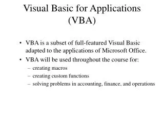
Visual Basic for Applications The Datapump Board Jamieson Olsen
Background I • D0 Central Track Trigger (CTT)
Background II • Trigger Electronics Low Voltage Differential Signal (LVDS) Channel Links
Background III • LVDS Channel Links The PROBLEM: Can’t probe the LVDS pairs! Can’t use a logic analyzer or ‘scope!
The Datapump • To debug our trigger hardware it would be useful to have a data pattern generator that would drive channel links. • Likewise, it would be good to have a board that could capture channel link data and read it out. • General purpose – it should work with AFE, Mixer, and DFE boards!
Hardware Interface Need some easy way to load test vectors into the transmitters and readout the captured data on the receivers. What’s the hardware interface?
Hardware Interface OK, use a PC! How should the PC connect to the Datapump? • VME is not portable • PCI, PCMCIA, USB, IEEE1394? Huh? • Parallel port is fast & easy to program! (More on this later…)
Datapump Board • Three medium-sized Field Programmable Gate Arrays (FPGAs) are used to build the transmitter and receiver circuits. • A small CPLD acts as the parallel port interface “bridge” to the FPGAs.
Transmitter Circuit • Each transmitter sends 128 28-bit words (loops continuously). • All ten transmitters are synchronized to the same counter and 53MHz clock. • The transmitter test vectors can be read back for verification.
Receiver Circuit • Specify a unique trigger pattern for each receiver. Should include ‘X’ (don’t care) bits. • All receivers are armed simultaneously. • Once armed, each receiver waits for the trigger pattern, then captures 256 data words.
Parallel Port • Enhanced Parallel Port (EPP) is used • 8-bit bi-directional datapath • Three “ports” in the PC I/O space: Control, Data, Address • Setup the control port, then… • To write a byte: outp(port, data) • To read a byte: inp(port)
Parallel Ports and VBA • VBA does not include the inp() and outp() functions. • VBA calls functions in a DLL (ntio.dll) called VB_pokeIO(port, data) and VB_peekIO(port) • The peek/poke functions in this DLL “cut through” windows and get right to the hardware ports.
User Interface • There are lots of test vectors which need to be visible simultaneously. • An Excel spreadsheet is ideal for this application! • VBA talks to the datapump via the parallel port.
Excel Control Buttons • Configure the datapump FPGAs. • Write/Verify the transmitter test vectors. • Specify the trigger pattern for each receiver. • ‘Arm’ and readback the receiver data.
Configuration • Must do this each time datapump is power cycled. • Originally this was a C program and DOS batch file, but it was all converted into VBA. • Writes three files to the datapump PLDs. • The VBA module is called HEXDUMP, calls two subs Vbwrite_C() and hexdump().
Datapump Transmitters VBA module “datapump”, subroutines Download_Vector() and Verify_Vector()
Datapump Receivers VBA module “datapump”, subroutines setup_U1() and readback_U1()