Download
1 / 43
430 likes | 453 Vues
This status report provides an overview of the current state of the n_TOF Facility, including the previous EPR, old target removal and investigation, pitting corrosion mechanism study, and proposed solution for the new target design. It also outlines the progress made towards restarting the facility, including simulations, measurements, and safety preparations.

E N D
Status Report by the n_TOF Technical Coordinator P. Cennini AB-ATB on behalf of the n_TOF Team • The n_TOF Facility • Where are we standing • Resume of the previous EPR • Old Target removal and Investigation • Pitting corrosion mechanism study • Solution studied for the New Target Design • Feasibility • Conclusions Second n_TOF External Panel Review, CERN, 14 February 2008
The n_TOF Facility Neutron production by spallation on Pb using a 20 GeV/c proton beam Neutron yield of one 20 GeV/c proton in a 2x2x2 m lead block: ~600 neutrons • Energy Spectrum: @1 eV to 250 MeV • Neutron Flux: 6.2´105 n/cm2/7x1012p • Flight path: 187.5 m • Duty Cycle: < 1 % • Energy Resolution: 0.02 % at 1 keV 0.2 % at 1MeV • Intrinsic in-beam Contamination: Gammas 10%, 1 % at 100 MeV • Outside-beam Contamination: <10-6 relative.
The n_TOF Facility main Parts • n_TOF Main Parts • The proton Line • The Target Area • The Flying path • The Sweeping Magnet • The Collimation • The Experimental Area • The Escape Line
Where are we standing:Facility running from Nov 2000 till Nov 2004 Integrated number of protons on target over the running period: ~6x10¹⁹ protons Detection of unusual radioactivity in the water filters (sieves)
Where are we standing: After the end of the Run in November 2004, the Facility has been stopped and the restart conditioned by the understanding of the problem. There is a request from the CERN management to study a solution to restart the Facility in 2008.
Last actions toward therestart of the Facility • Presentation to the First External Panel Review: done, report received. • Target removal: done (27.09.2007). • Study of the mechanism of the target corrosion: done • Simulations of the Target Activation: done • Simulations of the Pit and Pool Activation: done • Dose rate measurement of the old Target: done • Dose rate measurement in the Access Pit: done • Target sample taking: done • Target visual Inspection & photography: done. • Target laser surface inspection: done. • Pit & Pool visual inspection (web camera): done. • FLUKA Simulations for the geometry of the New Target: in progress. • Proposal for the New Target & Cooling System design: in progress. • Pre-design study for the target area ventilation: in progress. • Preparation of the Safety File: in progress. • Presentation to the Second External Panel Review
Resume of the previous EPR Assuming the following points satisfied: The control of air temperature and humidity in the Target Area. The minimization and control of the released air to the environment. The upgrade of the target water cooling circuit (containment) The cleaning to remove the activity from the walls in the existing piping. The control of the water chemistry: conductivity, pH, oxygen content, flow, pressure and temperature. The installation of a second ion exchanger. The use of metal seal in the heat exchanger. The Cooling circuit infrastructure design made to cope with the possible increase of radioactivity in the water. The implementation of all measures minimizing the target pitting corrosion. The preparation of a feasibility study with a detailed safety assessment. The organization of a documented HAZOP study to demonstrate the ability of the Facility to cope with a range of accident conditions. The restart of the Facility is justified
Old Target removal and InvestigationRemarks on the Target Visual Inspection Considering that: • There is a hole in the proton impact region due to pitting corrosion. • The modular assembly of separate lead blocks presents a mechanical instability. • The target shape don’t allow the correct water flow on the entrance face. • The target dimension could be reduced without significant reduction of the neutron flux. The reuse of the existing Target is excluded.
Old Target removal and InvestigationLaser Surface Survey (1)
Old Target removal and InvestigationLaser Surface Survey (2)
Old Target removal and InvestigationLaser Surface Survey (3) The deformation in the central block indicates a creep effect. This aspect of the lead behavior will be carefully estimated in the new target design.
Old Target removal and InvestigationRemarks on the Pool Visual Inspection Considering that: • There are contaminated oxide deposit on the floor and on the walls. • There are signs of corrosion on the proton entrance window. • The upgrade of the existing Cooling System is mandatory to cope with the unexpected release of radioactivity into the cooling plant and to maintain future contamination within reasonable limits. The reuse of the existing Cooling Circuit is not envisaged
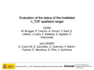
Pitting corrosion mechanism studyEvaluation of the status irradiated n_TOF Pb spallation targetCERN and CIEMAT D. Cano-Ott et al.[1] [1] https://edms.cern.ch/cedar/plsql/doc.info?cookie=7097488&document_id=881888&version=1
Acquired Experience • The old target design is showing some weak points: • Insufficient cooling, in particular at the hottest spots (proton entrance lead surface). • Mechanical instability due to non monolithic construction. • Lack of chemical stabilization of the cooling water, enhancing the probability of pitting corrosion. • By implementing the following points: • Provide a water flow on the proton entrance surface to maintain the local temperature lower than the boiling point. • Adopt a monolithic structure. • Monitor and Control the water chemistry: - oxygen sensor & degassing equipment in case of ultra pure water solution - oxygen sensor & pH control in case of bicarbonate based solution. The use of lead directly cooled by water remains a good choice.
Strategies to restart the Facility in 2008 The following options could be envisaged for the restart: Upgrading the existing cooling System and installation of a Target similar to the old one. Dismantling of the Target Area, installation of a new Target Assembly and Cooling System. Installation of a new Target Assembly via the shaft cooled by a new Cooling System.
Solution 1:Upgrading the cooling System,use a Target similar to the old one
Solution 1:Upgrading the cooling System,use a Target similar to the old one • The following points should be considered: • The status of the Pool and of the entrance and exit windows is not clearly assessed. • There are concerns on the life expectance of the windows (fatigue). • The use of the existing Pool is conditioned to the decontamination. • The upgrade of the cooling circuit needs interventions in TT2A [2].These interventions could lead to the practical rebuilding of the cooling system (water containment, heat exchanger, pumps, water quality monitor and control, etc.). • The access in the tunnel is limited to the shut-down period (the access doors to TT2A are in the PS interlock chain). • There are access restrictions during the run to monitor and control the chemistry of the cooling water. This solution can’t be achieved in 2008 due to the access restriction in the TT2-A tunnel. [2]https://edms.cern.ch/cedar/plsql/doc.info?cookie=7097488&document_id=881888&version=1
Solution 2: Dismantling of the Target Area& construction of a new Target Assembly • Considering that: • The access to the target area in the TT2A tunnel requires the dismantling of the shielding all along the vacuum tube [3]. • The last part of the shielding near the Target area is activated, requiring a high “cost” in terms of received dose for personnel (5 to 10 mSv). • The access in the tunnel is limited to the shut-down period (the access doors to TT2A are in the PS interlock chain). • The upgrade of the cooling circuit needs interventions in TT2A [2]. • The presence of Radioprotection technicians in the tunnel is needed over a long period of time. • The design of a new Target (and cooling?) is in any way needed. This solution has no chances to be implemented in 2008 and is not satisfying the ALARA Principle. [2][3]https://edms.cern.ch/cedar/plsql/doc.info?cookie=7097488&document_id=881888&version=1
Solution 3: New Target DesignInstallation via the shaft The following options were studied [4] to verify the possibility to use alternative solutions for the new target design: [4] https://edms.cern.ch/document/883348/1/TAB3
New Target Design:Activity and Dose rate comparison After 3 years of cooling Ø=60 cm
New Target Design:Neutron fluence lossesRatio of the neutron flux Old/New Ta Target
New Target Design:Neutron fluence lossesRatio Old/New for various lead diameters
New Target Design: Tantalum cylindersurrounded by lead, air cooled. Tantalum Rod Ø= 20 cm L= 30 cm Density = 16.69 ~157 kg Lead Øext= 55 cm Ømin= 32 cm L= 50 cm Density = 11.34 ~1074 kg ~1230 kg tot Advantages: all the water related problems are avoided (containment, activation, decontamination,...) Existing Pool Air distribution structure Air IN Air OUT • Disadvantages: • neutron flux reduction • Increased activation (handling and decommissioning) • Very high air flux (>700 m3/h) • Complex structure needed to distribute the air flux • Tantalum purchasing (cost & time) • Completely new design (no acquired experience) • Moderation (solid?, liquid?) Moderator Ta rod proton beam L=30 cm L=20 cm Pb (casted) Pb (casted)
New Target Design: Residual dose rates[mSv/h] for the Ta cylinder air cooled.
New Target Design:Cylindrical Lead Target, water cooled Water IN Water OUT AirIN Shielding Quick locks Existing Pool (Containment Vessel) Water distribution structure New Pressurized Vessel Moderator (5 cm) Ø=60 cm L=35 cm proton beam Pb (casted) Tap Water Tank (Storage) Lead Volume = 100 l, Density = 11.34 ~1130 kg
Strategy to restart the Facility in 2008 • Considering that: • The acquired experience with the old target is showing the ability of lead to work without serious mechanical damages over a large number of cycles (~5.2x10¹⁹ p). • The mechanism of the pitting corrosion has been studied and understood. • By building a new Cooling Circuit the safety requirements suggested by the External Panel could be implemented in agreement with the CERN Safety Rules. • The use of lead presents clear advantages in terms of reduced residual dose and self shielding. • The delivery in 2008 is mandatory The installation via the shaft of a new lead target cooled by pressurized water in the volume defined by the existing Pool is the solution under study
Items discussed in the following presentations Summary of theEnvisaged improvements • Design criteria for the Facility up-grade: • The use of a pressurized water cooling circuit • The double containment in the whole cooling circuit • The infrastructure to collect the contaminated water • The water flow control on the proton impact area • The continuous monitoring and control of the water chemistry • The proton beam optimization (enlargement of the beam impact crossection) • The use of a Pb alloy to boost the mechanical characteristics • Reduction of the target total mass (lead and supports)
Feasibility:View of the existing Pool Second containment for the new Target Assembly Third containment for the new Target Assembly
Feasibility:Pit lay-out • The Cooling Station is equipped with a closed Retention Vessel. • The piping between the Cooling Station and the New target Vessel is double-wall. • Any water leak in the Pit is collected in the old Pool via the Envelope (funnel). • The water collected in the Pool goes by gravity in an external accessible closed vessel. • In terms of dose rate and accessibility, the access to the connecting area in the pit during the installation and the decommissioning phase is possible.
Scheme for Cooling water replacementand Decommissioning Normal Working Condition Replacement 90% of the water (without Target removal) Emptying of the Target Container (Decommissioning) Air Compressor Water Tank (in the Service Gallery) Heat Exchanger Cooling Station Pump Main Water Tank (in the Cooling Station) Tap (remotely operated) Quick connections Air Lifting Shielding
Feasibility:Time-Scale Main items considered to evaluate the time-scale: The Target Cooling & Target Area Ventilation The Target Assembly For the Cooling and Ventilation the project phase consists on the choice of standard elements based on the specifications defined by the Target Assembly study. This phase is short compared to the installation of the various elements requiring hardware interventions and civil engineering works on the field. A delay of 6 months for the project and installation seems possible. For the Target Assembly the situation is opposite, in fact the design phase is requiring many simulations for the neutronics, thermal behavior, material fatigue, mechanics... Due to short installation time needed, 3 months design plus 4 months construction seems possible. Assuming a start in a “well defined direction” end of February 2008, the possibility to have a target ready 1st October 2008 is certainly challenging but (hopefully) realistic.
Conclusions • An important combined effort has been done during the last months to evaluate the status of the old Pb target. • Its status is well understood and a consensus on the mechanism responsible for the target present situation has been reached between CERN and the Collaboration. • CERN and the Collaboration are preparing an action plan to have a new target ready for running in 2008. • A complete and detailed engineering study is in progress. • The FLUKA simulations for the new geometry is in progress. • The Safety File preparation is in progress. • A HAZOP will be organized to show that the Facility can cope with a range of accident conditions.