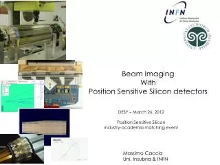
Beam Imaging with Diffraction Radiation
This document discusses diffraction radiation emitted when charged particles pass near a conducting target, generating radiation cones in both forward and backward directions. Key parameters include impact parameter, beam energy, and wavelength. Initial theories from the 1960s have evolved, with significant measurements reported from the LARP meetings since 1995. Observables such as near-field and far-field intensity, polarization, and angular distribution enable diagnostics of beam size, position, divergence, and energy. Future research aims to refine these methods and develop further collaborations for experimentation.


Beam Imaging with Diffraction Radiation
E N D
Presentation Transcript
Beam Imaging with Diffraction Radiation Tanaji Sen May 23, 2007
Diffraction Radiation Radiation emitted when a charged particle passes in the vicinity of a conducting target. Two cones (angle ~ 2/γ ) of radiation in the forward and backward direction Key parameters: the impact parameter, beam energy and wavelength of radiation Similar (and different) to transition radiation where a particle passes through the conducting target. Main advantage: Non-invasive (mostly!) Initial theory developed: ~ 1960s First measurements reported: ~1995 LARP Meeting - Diffraction Radiation
Possible Beam Diagnostics Diffraction Radiation Observables • Near field (at target) and far field intensity • Polarization • Frequency spectrum • Far field angular distribution These can be combined to measure • Beam size • Beam position • Beam divergence • Energy Easier with far-field (Fraunhofer diffraction) than with near-field (Fresnel diffraction) LARP Meeting - Diffraction Radiation
Diffraction Radiation - Layout CCD or PMT Filter Polarizer Far field imaging at KEK Phys. Rev Letters 90, 104801 (2003) 93, 244802 (2004) Near field image at APS PRSTAB:10,022802(2007) BDR 2Φ FDR Target Proton beam Beam b Impact parameter Φ LARP Meeting - Diffraction Radiation Target
KEK results Imax Imin LARP Meeting - Diffraction Radiation
Key parameters Choose: λ = 1000 nm (near IR); t = 2π b/γλ = 1; Intensity of DR ~ e-t = e-ω/ωc Impact parameter b = 15σ (LHC requirement) LARP Meeting - Diffraction Radiation
Required beam size • RHIC: At 4000nm, σ ~10 μm. Not feasible ? • Tevatron. At 4000nm, σ ~45 μm. Within ~0.5m from B0/D0 Min σ(arc) ~ 290 μm. Far infra-red? • LHC At 1000 nm, σ ~79. μm. Within 20m of IP LARP Meeting - Diffraction Radiation
IP5: Horizontal Crossing Angle Layout in the LHC IP1 : Vertical Crossing Angle BDR Cone Beam 2 b Target at 45 to beam direction b Beam 1 Location - Both beams should not arrive at the same time BDR Cone LARP Meeting - Diffraction Radiation
Further Developments Interference from multiple apertures Different Target Shapes to remove pre-wave zone effects Theory needs to be developed for - near field intensity with different aperture shapes - finite target size Beam Interference pattern is sensitive to beam divergence LARP Meeting - Diffraction Radiation
Criteria for ODR • What diagnostics does it realistically provide? • Precision and reliability of measurements (understand systematic and random errors) • Advantages/disadvantages of ODR • Impact on the machine and detector • Does it advance the start of the art? LARP Meeting - Diffraction Radiation
Next Steps • Explore the prospects of measuring ODR in a storage ring: Tevatron, APS, ALS, PEPII, …. • Develop an informal collaboration with US labs and CERN • Understand better the challenges of near field and far field imaging • Develop a proposal for experiments at an existing facility • Present proposal to the LARP collaboration for funding • Proceed with experiments • Develop ODR facility for the LHC LARP Meeting - Diffraction Radiation