Advances in Image and Video Compression Standards: From G3 Fax to MPEG-4
This overview outlines the evolution of international standards for image and video coding, covering pivotal developments from the 1980s to the 2000s. Key milestones include the introduction of ITU-T T.4 and T.6 for fax, JPEG for still images, JBIG for bi-level pictures, and significant MPEG advancements. The standards support diverse applications in multimedia, from facsimile transmission to high-definition video. This document highlights essential techniques, algorithm enhancements, and contributions to various fields, reflecting on the impact of these standards on multimedia communication and technology.

Advances in Image and Video Compression Standards: From G3 Fax to MPEG-4
E N D
Presentation Transcript
International Standards for Image/Video Coding
Multimedia Everywhere • Towards Multimedia : Consumer Computer Electronics Multimedia Tele- Communication Broadcasting
Still Picture Compression Standards • 1980 : ITU-T T.4 : G3 FAX for PSTN Modified Huffman and Modified READ • 1984 : ITU-T T.6 : G4 FAX for ISDN Modified MR • 1992 : JPEG (ISO 10918, ITU-T T.81) : Color Still Pictures used for Color Fax, Electronic Still Camera, Color Printer, Computer Applications etc Lossless/Lossy Modes, Baseline/Extended Modes, Progressive/Sequential Modes DPCM + DCT + Q + RLE + Huffman/Arithmetic Codes Motion JPEG can be used for Moving Pictures. • 1993 : JBIG (ISO 11544, ITU-T T.82) : Bi-level Pictures Improvement on T.4 and T.6 • Recently: JPEG-LS, JBIG2, etc
Moving Picture Compression Standards • 1982 : ITU-R BT.601 : Studio Quality PCM Component Video Common to 525/60 and 625/50 Systems 13.5 MHz Sampling, 8 bit/sample, 4:2:2 Format • 1990 : ITU-T H.261 : Video Phone/Conference Application via ISDN Bitrate = p x 64 kbps, p = 1-30 MC DPCM + DCT + Q + RLE + Huffman Codes Reference Model 1 - 8 • 1992 : MPEG-1 Video : DSM Applications (e.g. Video CD) Bitrate = 1.5 Mbps MC DPCM + DCT + Q + RLE + Huffman Codes GOP Structure for Random Access and Error Recovery (I, P, B Frames) Simulation Model 1 - 3
Moving Picture Compression Standards (Continued) • 1994 : MPEG-2 Video (ISO 13818-2, ITU-T H.262) : Generic Algorithm for Various Applications (Broadcasting, Communication, Network, DSM etc) 5 Profiles of Functionality (Simple, Main, Spatial Scalable, SNR Scalable, High) 4 Levels of Resolution (Low, Main, High-1440, High) Deals with Interlaced Scan as well as Progressive Scan Field/Frame ME & DCT, Dual Prime ME, Intra VLC, Altenate Scan, Nonuniform Q, etc • 1993 : ITU-R CMTT.721 : 140 Mbps Contribution Quality Video Adaptive DPCM, Componentwise • 1993 : ITU-R CMTT.723 : 34-45 Mbps Contribution Quality Video MC DPCM + DCT + Q + RLE + Huffman Codes
Moving Picture Compression Standards (Continued) • 1995 : ITU-T H.263 : Videophone via PSTN Bitrate < 64 kbps (V.34 modem = 33.6 kbps, Recent modem = 56 kbps) Improved version of H.261 • 1998 : MPEG-4 Bitrates < 2 Mbps Targets: Multimedia data base access Wireless multimedia communication Components of H.263 are incorporated Content-based compression Synthetic and natural video/audio Multiple tools/algorithms/profiles => Flexibility • 1999 : MPEG-4 Version 2, MPEG-7
Bilevel image compression standards • ITU-T recommendation T.4(G3 Fax) and T.6(G4 Fax) Application : facsimile(transmission of bilevel documents) Coding scheme - G3 : 1-D nonadaptive run-length + Huffman 2-D nonadaptive run-length + Huffman - G4 : 2-D nonadaptive run-length + Huffman References - G3: ITU-T Recommendation T.4, “Standardization of Group 3 Facsimile Apparatus for Document Transmission,” - G4: ITU-T Recommendation T.6, “Facsimile Coding Scheme and Control Functions for Group 4 Facsimile Apparatus”. - Rafael C. Gonzalez, Richard E. Woods “Digital Image Processing”, Addison Wesley, 1992 - Anil K. Jain, “Fundamentals Of Digital Image Processing”, Prentice-Hall, 1989
Continuous-tone still image compression standards • JPEG(Joint Photographic Experts Group) Applications : color FAX, digital still camera, multimedia computer, internet JPEG Standard consists of -a lossy baseline coding system - an extended coding system for greater compression, higher precision or progressive reconstruction applications - a lossless independent coding system for reversible compression References - ITU-T recommendation T.81, “Information Technology - Digital compression and Coding of Continuous-Tone Still Images - Requirements and Guideline”, 92. 2 - K. R. Rao, J. J. Hwang, “Techniques & Standards for Image, Video & Audio Coding”, Prentice Hall PTR, 1996
Baseline system • Baseline system : most widely used among JPEG standards Data precision - 8 bits for input and output - 11 bits for quantized DCT coefficients Algorithm - DCT + quantization + variable length coding Compression Guideline - 0.25 ~ 0.5 bits/pixel : moderate to good quality, some applications - 0.5 ~ 0.75 bits/pixel : good to very good quality, many applications - 0.75 ~ 1.5 bits/pixel : excellent quality, most applications - 1.5 ~ 2.0 bits/pixel : indistinguishable (visually lossless) quality, most demanding applications
Baseline system block diagram • Baseline system encoder • Baseline system decoder
FDCT and IDCT • Two-dimensional FDCT and IDCT Zero shift for input signal - [0, 2p- 1] [ - 2p-1, 2p-1 - 1 ] ( p=8 or 12 ) reduce the internal precision requirement in the DCT calculation 88 DCT - efficient energy compaction(close to KLT) - blocking artifacts at high compression ratios Definition - Fast FDCT and IDCT algorithms exist, e.g. Lee algorithm.
Quantization and inverse quantization • Quantization table - No default values for quantization tables - Application may specify the tables - Q(u, v) : quantization table integer value from 1 to 255
Example f (x,y) F (u,v) FQ (u,v) Quant. FDCT e (x,y) r (x,y) Inverse Q & IDCT
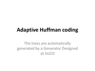
Entropy Coding • DC Coefficient Coding Differential Coding DC coefficients of adjacent blocks are strongly correlated. VLC(Huffman Coding)
Entropy Coding (cont.) • AC coefficients Coding - Zigzag Scanning - VLC(Variable Length Coding, Huffman Coding)
Example Zigzag scanning [39, -3, 2, 1, -1, 1, 0, 0, 0, 0, 0, -1, EOB] (run, value) assuming : DC coefficient of previous block = 35 [5, (0,-3 ), (0,2 ), (0,1 ), (0,-1), (0,1), (5,-1), EOB] dc(cat, value), ac( run/cat, value) [dc(3, 5), ac(0/2,-3 ), ac(0/2,2 ), ac(0/1,1 ),ac(0/1,-1 ), ac(0/1, 1), ac(5/1,-1), EOB] Entropy Coding [100 101 / 01 00 / 01 10 / 00 1 / 00 0 / 00 1 / 1111010 0 / 1010] 512 bits 35bits
JPEG Compression Examples Original image (24bpp) JPEG Compressed image ( 32:1 -- 0.75bpp ) JPEG Compressed image (8:1 -- 3bpp) JPEG Compressed image ( 128:1 -- 0.1875bpp )
MPEG Digital Video Technology • MPEG-1( ISO/IEC 11172 ) and MPEG-2( ISO/IEC 13818 ) Applications : MPEG-1 : Digital Storage Media(CD-ROM…) MPEG-2 : Higher bit rates and broader generic applications ( Consumer electronics, Telecommunications, Digital Broadcasting, HDTV, DVD, VOD, etc. ) Coding scheme : Spatial redundancy : DCT + Quantization Temporal redundancy : Motion estimation and compensation Statistical redundancy : VLC References : - ISO/IEC 11172-2 (MPEG-1), ISO/IEC 13818-2 (MPEG-2) - K.R.RAO and J.J. HWANG, “TECHNIQUES & STANDARDS FOR IMAGE•VIDEO & AUDIO CODING,” Prentice Hall, 1996.
MPEG Overview • MPEG : • - Motion Picture Experts Group • - Specifies a standard compression, transmission, and decompression scheme • for video and audio. • - ISO/IEC 11172 : MPEG-1 • - ISO/IEC 13818 : MPEG-2 • - Consists of 3 parts. • Part 1 : System • Part 2 : Video • Part 3 : Audio
MPEG System Structure • MPEG System Stream Structure MPEG system stream is made up of two layers - System layer : timing and other information demultiplex and synchronize the audio and video streams - Compression layer : audio and video streams • General Decoding Process
Video Stream Data Hierarchy • Video Stream Data Hierarchy Video Sequence - Begins with a sequence header (may contain additional sequence headers). - Includes one or more groups of pictures, and ends with an end-of-sequence code. Group of Pictures (GOP) - A header and a series of one or more pictures intended to allow random access into the sequence.
Video Stream Data Hierarchy (Cont.) Picture - The primary coding unit of a video sequence. - Consists of three rectangular matrices representing luminance (Y) and two chrominance (Cb and Cr) values. Slice - One or more ``contiguous'' macroblocks. - Slices are important in the handling of errors. If the bitstream contains an error, the decoder can skip to the start of the next slice. Macroblock - A 2 by 2 section of Block ( 4 Y blocks + 1 Cb block + 1 Cr block ) - Basic unit for motion estimation and motion compensation Block - A block is an 8-pixel by 8-line set of values of a luminance or a chrominance component. - Basic unit for DCT ( discrete cosine transform )
MPEG compression of Video • How to remove spectral, spatial, temporal, and statistical redundancy?
Spatial redundancy • Pixel Coding using the DCT • As human eyes are insensitive to HF color changes, the R,G, B signal is • converted into a luminance and two color difference signals. We can remove • redundancy more on U, V than on Y. • The top left DCT component is taken as the dc datum for the block. • DCT coefficients to the right are increasingly higher horizontal spatial freqs. • DCT coefficients below are higher vertical spatial frequencies.
Spatial redundancy (Cont.) • Quantization & Entropy coding This all has a cost. That is shown in the pictures below: the upper picture is unquantized, the lower one quantized • The higher the DCT frequency is, the greater the Quant Matrix value • becomes. This makes many coefficients go to zero • To generate efficient (Run, Level) symbols, Zig-zag scanning is applied to • the quantized 88 DCT coefficients
Two scanning methods of the DCT coefficients in MPEG-2 (a) Zigzag scan (b) Alternate scan • Zigzag scan is typical for progressive (noninterlaced) mode processing. • Alternate scan is more efficient for interlaced format video.
Chrominance Format • There are three formats : - 4:4:4… the chrominance and luminance planes are sampled at the same resolution. - 4:2:2… the chrominance planes are subsampled at half resolution in horizontal direction. - 4:2:0… the chrominance planes are subsampled at half resolution in both horizontal and vertical directions.
Temporal redundancy • Inter-frame prediction & motion estimation • This really reduces the overall bit rate from frame to frame
Putting it all together • I, P, B Frames • The Intra Frames contain full picture information • Predicted(P) Frames are predicted from past I, or P frames • Bi-directional predicted frames offer the greatest compression and use past and future I & P frames for motion compensation.
MPEG-2 Level and Profiles This expandability of MPEG-2 format allows it to serve the needs of many different kinds of application. This is aided by defining several levels of decoders, and several profiles of video source.
Upperbound parameters in profile and levels Note: Numbers in parentheses refer to the enhanced layers.
Building the Elementary Stream • This slide shows how the actual blocks, slices, frames etc. are all put together to form the elementary stream • Along with the actual picture data, header information is required to reconstruct the I, B, P frames. This header structure is shown. • The next stage is to take this ES and convert it into something that can be transmitted and decoded at the other end.
Ordering frames for decoding • The PTS & DTS • In odering for a decoder to reconstruct a B-frame from the preceding I and following P frames, both these must arrive first. • So the order of frame transmission must be different from the order they appear on the TV screen.
Ordering frames for decoding (Cont.) • The decoder must also know at what time it should show the frames. That is their • order in time. • The Decoding Time Stamp(DTS) : • tells the decoder when to decode the frame. • The Presentation Time Stamp(PTS) : • tells the decoder when to display the frame. • In addition, a clock must be embedded, to allow a time reference to be created. • In MPEG-1, the clock is 33 bits with 90 kHz input; while in MPEG-2, the clock is 42 bits with 27 MHz input • The clock, known as the Programme Clock Reference(PCR), is contained in the • Transport Stream(TS). The System Clock Reference(SCR) is used in the • Programme Clock Reference(PCR) and in the MPEG-1 system stream.
Ordering frames for decoding (Cont.) • Frame Reordering
MPEG-2 Transport Stream • Multiplexing many programs