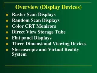
Overview (Display Devices)
Overview (Display Devices). Raster Scan Displays Random Scan Displays Color CRT Monirors Direct View Storage Tube Flat panel Displays Three Dimensional Viewing Devices Stereoscopic and Virtual Reality System. Overview (Display Devices).

Overview (Display Devices)
E N D
Presentation Transcript
Overview (Display Devices) • Raster Scan Displays • Random Scan Displays • Color CRT Monirors • Direct View Storage Tube • Flat panel Displays • Three Dimensional Viewing Devices • Stereoscopic and Virtual Reality System
Overview (Display Devices) • The display systems are often referred to asVideo MonitororVideo DisplayUnit (VDU).
Display Hardware • Video Display Devices • The primary output device in a graphics system is a monitor.
Video Monitor Cathode Ray Tube (CRT)
Electron Guns Electron Beams Focusing Coils Deflection Coils Anode Connection Shadow Mask Phosphor layer Close-up of the phosphor coated inner side of the screen
Refresh CRT • Light emitted by the Phosphor fades very rapidly. • Refresh CRT: One way to keep the phosphor glowing is to redraw the picture repeatedly by quickly directing the electron beam back over the same points.
Electron Gun • Heat is supplied to the cathode by the filament.
Electron Gun • The free electrons are then accelerated toward the phosphor coating by a high positive voltage.
High Positive Voltage • A positively charged metal coating on the inside of the CRT envelope near the phosphor screen. A positively charged metal
High Positive Voltage • An accelerating anode .
Electron Gun • Intensity of the electron beam is controlled by setting voltage level on the control grid.
Electron Gun • A smaller negative voltage on the control grid simply decrease the number of electrons passing through.
Focusing System • The focusing system is needed to force the electron beam to converge into a small spot as it strikes the phosphor. • Electrostatic focusing is commonly used in computer graphics monitor.
Focusing System • With electrostatic focusing, the electron beam passes through a positively charged metal cylinder that forms an electrostatic lens.
Focusing System • Similar lens focusing effects can be accomplished with a magnetic field set up by a coil mounted around the outside of the CRT envelope.
Focusing System • The distance that the electron beam must travel to different points on the screen varies because the radius of curvature for most CRTs isgreater than the distance from the focusing system to the screen center.
Focusing System • The electron beam will be focused properly only at the center of the screen. • As the beam moves to the outer edges of the screen, displayed images becomeblurred. • Dynamically focusing lens work based on beam position.
Deflection Systems • Deflection of the electron beam can be controlled either with electric fields or with magnetic fields. • The magnetic deflection coils mounted on the outside of the CRT envelope.
Deflection Systems • Two pairs of coils are used, with the coils in each pair mounted on opposite sides of the neck of the CRT envelope.
Deflection Systems • One pair is mounted on the top and bottom of the neck, and the other pair is mounted on opposite sides of the neck.
Deflection Systems • Horizontal deflection is accomplished with one pair of coils, and vertical deflection by the other pairs. • The proper deflection amounts are attained by adjusting the current through the coil.
Deflection Systems • Electrostatic deflection: Two pairs of parallel plates are mounted inside the CRT envelope.
Deflection Systems • One pair of plates is mounted horizontally to control the vertical deflection, and the other pair is mounted vertically to control horizontal deflection.
Spots of Light • Spots of lights are produces on the screen by the transfer of the CRT beam energy to the phosphor. • Part of the beam energy is converted into heat energy.
Spots of Light • The excited phosphor electrons begin dropping back to their stable ground state, giving up their extra energy as small quantums of light energy.
Persistence • Persistence :The time it takes the emitted light from the screen to decay to one-tenth of its original intensity.
Intensity Distribution • The intensity is greatest at the center of the spot, and decrease with Gaussian distribution out to the edges of the spot.
Resolution (Spots of Light) • Resolution: The maximum number of points that can be displayed without overlap on a CRT. Overlap
Resolution (Spots of Light) • Resolution of a CRT is dependent on: • The type of phosphor • The intensity to be displayed • The focusing and deflection systems. Typical resolution: 1280 by 1024
Aspect Ratio • Aspect Ratio: This numbers gives the ratio of vertical points to horizontal points necessary to produce equal length lines in both directions on the screen.
Electron Guns Electron Beams Focusing Coils Deflection Coils Anode Connection Shadow Mask Phosphor layer Close-up of the phosphor coated inner side of the electron
Cathode Ray Tube (CRT) Beam passing through mask Anode Connection Shadow mask Electron Beam Deflection Coils Electron Gun
Raster Scan Displays • Raster: A rectangular array of points or dots • Pixel: One dot or picture element of the raster • Scan Line: A row of pixels
Raster Scan Displays • In a raster scan system, the electron beam is swept across the screen, one row at a time from top to bottom.
Raster Scan Displays • As the electron beam moves across each row, the beam intensity is turned on and off to create a pattern of illuminated spots.
Raster Scan Displays • Picture definition is stored in a memory area called the refresh buffer or frame buffer.
Raster Scan Displays • Refresh buffer or frame buffer: This memory area holds the set of intensity values for all the screen points.
Raster Scan Displays • Stored intensity values then retrieved from refresh buffer and “painted” on the screen one row (scan line) at a time.
Raster Scan Displays • Intensity range for pixel positions depends on the capability of the raster system. • A black-and-white system: each screen point is either on or off, so only one bit per pixel is needed to control the intensity of screen positions.
Raster Scan Displays • On a black-and-white system with one bit per pixel, the frame buffer is called bitmap. • For system with multiple bits per pixel, the frame buffer is called pixmap.
Raster Scan Displays • Sometimes, refresh rates are described in unit of cycles per second, or Hertz (HZ)
Raster Scan Displays • Refreshing on raster scan displays is carried out at the rate 60 to 80 frame per second.
Raster Scan Displays • Horizontal retrace: The return to the left of the screen, after refreshing each scan line.
Raster Scan Displays • Vertical retrace: At the end of each frame (displayed in 1/80th to 1/60th of a second) the electron beam returns to the top left corner of the screen to begin the next frame.