Download
1 / 27
280 likes | 603 Vues
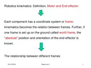
Robotics kinematics: Definition, Motor and End-effector Each component has a coordinate system or frame : kinematics becomes the relation between frames. Further, if one frame is set up on the ground called world frame , the “ absolute ” position and orientation of the end-effector is known.

E N D
Robotics kinematics: Definition, Motor and End-effector Each component has a coordinate system or frame: kinematics becomes the relation between frames. Further, if one frame is set up on the ground called world frame, the “absolute” position and orientation of the end-effector is known. The relationship between different frames Hand out 4
End-effector World frame Hand out 4
How to set up or assign a local frame to each component of the robot? What is called a component? What is called a joint? Hand out 4
World frame Hand out 4
Robot Kinematics: Logics of presentation: Kinematics: what Coordinate system: way to describe motion Relation between two coordinate systems Definition of component and joint: robot structure handout 3
Link: Component with only considering its joint line but neglecting its detailed shape. Next slide (Fig. 2-21) shows various types of joints Hand out 4
Fig. 2-21 Joint types Kinematic pair types Neglecting the details of the joint but relative motions or relative constraints between two connected links Degrees of freedom of joint: the number of relative motions between two links that are in connection Hand out 4
General configuration of link Fig.2-22 Hand out 4
From axis i-1 to axis i The geometrical parameters of the general link are: - The mutual perpendicular distance:, a i-1 - The link twist, i-1 From axis i-1 to axis i Fig. 2-23 shows two links that are connected, which leads to the following geometrical parameters: - d i : link offset - : joint angle From axis a(i-1) to axis a(i) along axis i From axis a(i-1) to axis a(i) Hand out 4
Fig. 2-23 Hand out 4
Denavit-Hartenberg (D-H) notation for describing robot kinematic geometry. It has the benefit that only four parameters can describe completely robot kinematic geometry. The shortcoming is that they are always across two links. Hand out 4
Labeling of links: towards a unified representation • The base link or ground 0. • The last link n. • For other links (i=1, 2, …., n-1), their parameters will follow the D-H rule. However, for the link 0 and link n, there are some arbitrary situation. For instance, for the example in the next slide, there is no rule to constrain the definition of z0 and x3. This will be further discussed later when the local frame is assigned to each link. • It may also be clear that the geometrical parameters based on the D-H are dependent on the way of assigning or defining local frames to links. Hand out 4
All Z axes are all perpendicular to the paper plane Hand out 4
Robot Kinematics: Logics of presentation: Kinematics: what Coordinate system: way to describe motion Relation between two coordinate systems Definition of component and joint: robot structure Assign a local frame to each link (D-H notation) handout 3
- Regarding d1 (dn) and θ1 (θn), the rule is to make them 0.0 a) If joint 1 is revolute, define the base frame and the first frame such that d 1 =0.0, and θ1=0.0 at the initial time b) If joint 1 is prismatic, define the base frame and the first frame such that d1 =0.0 at the initial time, and θ1=0.0. c) If joint n is revolute, define the last frame and the n-1 frame such that d n =0.0, and θn=0.0 at the initial time d) If joint n is prismatic, define the last frame and the n-1 frame such that dn =0.0 at the initial time, and θn=0.0. Hand out 4
Rule to assign a frame to each link (intermediate links) • The Z-axis of frame (i), Zi , is coincident with the joint axis i. The origin of frame (i) is located where the aiperpendicularly intersects with the joint iaxis. Xipoints along aiin the direction from joint ito joint i+1. • In the case of ai= O, Xiis normal to the plane of Zi and Zi+1.We define aias being measured in the right-hand sense about Xi, so we see that the freedom of choosing the sign of α; in this case two choices are available. Hand out 4
Yi is formed by the right-hand rule to complete the i-th frame. Fig.2-24 shows the location of frames {i-1} and {i} for a general manipulator. Fig. 2-24 Hand out 4
Firstandlastlinksinthechain: Attach a frame to the base of the robot, or link 0, called frame (0). This frame can be treated as a reference frame for measuring the position and orientation of all other frames. Since frame (0) is arbitrary, it always simplifies matters to choose Z0 along axis 1 and to locate frame (0) so that it coincides with frame (1) when joint variable 1 is zero. Using this convention we have: ao= 0.0, αo = 0.0. Additionally, this ensures that d1= 0.0 if joint 1 is revolute, or θ1 = 0.0 if joint 1 is prismatic. Hand out 4
For joint n to be a revolute one, the direction of XNis chosen so that it aligns with X N-1when θN= 0.0, and the origin of frame (N) is chosen so that dn = 0.0. For joint n to be a prismatic one, the direction of XN is chosen so that θN = 0.0, and the origin of frame (N) is chosen at the intersection of X N-1and joint axis n when dn= 0.0. Summaryofthelinkparametersintermsofthelinkframes If the link frames have been attached to the links according to our convention, the following definitions of the link parameters are valid: ai= the distance from Zi to Zi+1, measured along Xi; Hand out 4
di = the distance from Xi_, to Xi-1 measured along Zi; and i, = the angle between Zi, and Z i+1measured about Xi. i = the angle between X i-1 and Xi, measured about Zi; We usually choose ai> 0 since it corresponds to a distance; however, other three are signed quantities. Hand out 4
A final note on uniqueness is warranted. The convention outlined above does not result in a unique attachment of Frames to links. First of all, when we first align the Zi axis with joint axis i, there are two choices of direction in which to point Zi. Furthermore, in the case of intersecting joint axes (i.e., ai= O), there are two choices for the direction of Xi, corresponding to the choice of signs for the normal to the plane containing Zi and Zi+1,. When axes i and i+1 are parallel, the choice of origin location for (i) is arbitrary (though generally chosen in order to cause di to be zero). Hand out 4
Example 1 Fig.2-25 Hand out 4
Fig.2-26 Hand out 4
Example 2 Hand out 4
Parameter table to be given in the classroom Hand out 4
Summary • Link and joint concept. • D-H notation for link. • Assign frames to links based on D-H. • Benefit of D-H: a minimum number of parameters to describe links and joints. • Shortcoming of D-H: parameters must cross two consecutively connected links. Hand out 4