Download
1 / 1
20 likes | 192 Vues
The Central Logic Board for the optical module of the KM3NeT detector . Paolo Musico on behalf of KM3NeT collaboration. I.N.F.N . Genova – via Dodecaneso , 33 – 16146 – GENOVA (Italy ). Abstract

E N D
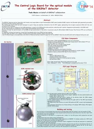
The Central Logic Board for the optical moduleof the KM3NeT detector Paolo Musicoon behalf of KM3NeT collaboration • I.N.F.N. Genova – via Dodecaneso, 33 – 16146 – GENOVA (Italy) Abstract The KM3NeT deep sea neutrino observatory will include a very large number of multi-Photomultiplier (PMT) optical modules (DOM) to detect the Cherenkov light generated by secondary particles produced in neutrino interactions. The Central Logic Board (CLB) has been developed to acquire timing and amplitude information from the PMT signals, implementing time-to-digital conversion (TDC) with time over threshold (TOT) technique. The board is also used to configure all the DOM subsystems, to assist in the DOM position and orientation, calibration and to monitor temperature and humidity in the DOM itself. All the collected data are transmitted to shore using a wide-bandwidth optical network. Moreover, through the optical network, all the DOMs are kept synchronized in time within 1 ns precision using the White Rabbit (WR) Precision Time Protocol (PTP) over an Ethernet connection. To implement all these functionalities, a large Field Programmable Gate Array (FPGA) has been adopted. The logic inside the FPGA is very complex, including two microprocessor systems running concurrent code. A set of CLB prototypes is now operational, and a batch of 50 pieces has been ordered to equip the first two KM3NeT detection units (DU) which will be deployed during next year. • CLB Main Components • Xilinx Kintex-7 FPGA (XC7K160TBG676) is the core of the board • Tunable oscillators (20 MHz and 25 MHz base frequencies) for White Rabbit PTP core • 512 Mbit Quad SPI Flash Eprom • PMT interface (31 x) through Octopus boards • SFP laser module housing with heatsink • Temperature & Humidity sensor • Compass & Tilt meter • NanoBeacon (calibration LED Flasher) Interface • Acoustic AES interfaces for Hydrophone and Piezoelectric acoustic sensors • Expansion industry standard FMC High Pin Count connector • Debugging: • Serial to USB converter (2 x) • Standard Header 20 pin connector • High density connector for batch production testing • Dip-Switches & LEDS • Power supply through Power Board (sits underneath the CLB) • Power consumption: < 4.5 W Total DOM power consumption will be about 7.5 W DU Section CLB Prototype Vertical Electro Optical Cable (VEOC) PPS IP/UDP Packet Buffer Stream Selector (IPMUX) 31 TDCs Break Out Box (BOB) Fifo 31 TDC Data RxPacket Buffer 64KB RxPort 1 RxPort 2 Rx_mac2buf Rx_buf2data Rx Stream Select 31 PMTs Flags Management & Control RxPort_m Management & Config. Pause Frame Fifo AES decoder Hydrophone & Piezo TxPacket Buffer 32KB TxPort 1 Management & Control TxPort 2 Tx_pkt2mac Tx_data2buf Tx Stream Select Flags Fifo TxPort_m Compass, Tilt, Temp Management & Config. Management & Control Data Control CPU UART I2C AMBA/Wishbone bus MEM UTC time, Clock & PPS RS232 Debug • CLB Logic Diagram • Two microprocessor systems based on LM32 soft processor: • White Rabbit Precision Time Protocol engine: implement 1ns time synchronization and transfer data to shore station • Configuration and slow control: handles all the devices inside the DOM, manage housekeeping data and implement debug ports • 31 TDC channels measure the arrival time and the pulse width of the PMT discriminated signals with 1ns resolution • The IPMUX block main function is to build UDP packet with PMT, acoustic and housekeeping data • Three European institutions are actively working on the design: INFN (Italy), IFIC (Spain), NIKHEF (Netherlands) ROPES DOM exploded view CLB OCTOPUS DOM external view Building and testing The first batch of 8 prototypes have been built by mid December 2013 and tested in the first months of 2014. A second batch of 12 prototypes (with some marginal modifications) have been delivered at the end of April 2014 and extensive tests are in progress. Preserie production of 50 pieces is in progress and a tender for the 600 pieces batch production has been assigned. All subsystems have been deeply tested independently. The first test bench for the whole DOM is under preparation at NIKHEF. It includes a whole set of PMT (with bases), two Octopus boards, one CLB, one Power Board. WR PTP has been tested with 200 Mbit/s Ethernet traffic originated in the CLB and connected to a dedicated switch together other data generators. The CLB will be used also as controller in the Base Container placed on the sea floor at the bottom of the DU. It will handle all the power control switch and the optical components needed to operate the DU. In this case a custom FMC mezzanine will be used to interface the various parts of the DU base.