Download
1 / 16
160 likes | 385 Vues
The Crab Nebula in the Infrared: A Review. PAOLO PERSI. 1. OUTLINE. Why Infrared Observations of the Crab A brief history of the IR observations of the Crab Infrared polarimetric imaging of the Crab Future IR observations of the Crab. 2. Why IR observations of the Crab. Chandra X-ray

E N D
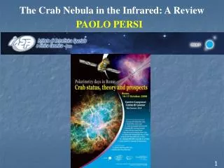
The Crab Nebula in the Infrared: A Review PAOLO PERSI 1
OUTLINE • Why Infrared Observations of the Crab • A brief history of the IR observations of the Crab • Infrared polarimetric imaging of the Crab • Future IR observations of the Crab 2
Why IR observations of the Crab Chandra X-ray Hubble SpascTelescope Spitzer space tetescope -To test the hypothesis that part of the interstellar dust does originate from SNe. The infrared (IR) is an ideal spectral region in which to test these theories, because dust grains emit strongly in the IR -To compare the spectral index derived from IR observations with those obtained in the different spectral regions such as UV-Opt. and radio. 3
1-5 μm (α=-0.65) AV=1.5 mag AV=1.75 mag 2.2μm • Conclusions: • The observed spectral index support the synchotron mechanism in the near-IR • The 2.2μm image is consistent with the visible flux distribution. • c) A spectral break is expected around 50 μm as derived interpolating infrared and radio data. 4
IRAS 60μm IRAS observations revealed significant excess emission, above the synchrotron spectrum peaking between 60 and 100μm. Strom & Greidanus 1992 Nature 358,654 have interpreted this excess asdue thermal radiation by dust at a temperature of 46 K and Md=0.02 MSUN Conclusions: The overall IR radiation is dominated by cold dust thermal emission at long wavelengths, and by synchrotron radiation at shorter wavelengts (<25μm) 5
ISOPHOT 60,100,and 170μm [OIII] 44arcsec 47 arcsec The dust emission at 60 and 100 μm is consistent with a small amount of warm dust (0.01–0.07MSUN of silicate at temperatures around 45 K or 0.003–0.02MSUN of graphite at temperatures around 50 K). The geometry of this warm dust emission is consistent with a torus of diameter ≈0.8 pc, presumably created by the supernova progenitor. 6
Contour map of [Fe II] 1.644μm a) Discovery of [Fe II] and H21-0 S(1) emission line in two filaments b) H2 1-0 S(1) line may be formed early in the expansion of the remnant when the densities were higher. Continuum- subtracted [Fe II] 1.644μm image The [FeII] image is very similar to [Ni II] λ7378 showing that Fe and Ni have the same gas phase distriburion within the nebula. 7
ISOCAM CVF Specro-Imaging: 6.5μm to 16μm 1) A filamentary structure is observed in the [NeIII] image. These filaments similar to the structure seen in the optical ionic lines are know to be composed predominately of supernovaejecta. 2) No dust can be observed at mid-IR 3) The mid-IR spectral index of the synchrotron radiation in the Crab Nebula varies from −0.3 to −0.65 according to the distance to the pulsar α=-0.5 8
optical 3.6μm SPITZER IMAGES OF THE CRAB • IRAC [3.6,4.5,5.8,8.0]: 0.86”/pix • MIRAC[24, 70] : 2.5-4.0”/pix 1) 3.6 and 4.5 μm images are dominated by continuum synchrotron emission. The ratio of the 3.6 and 4.5 μm images reveals a spatial variation in the synchrotronpower-law index ranging from approximately -0.3 to -0.8 across the nebula. 2) The 8.0 μm image, made with a bandpass that includes [Ar II] 7.0 μm, resembles the general morphology of visible Hα and near-IR [Fe II] line emission. 3) The 24 and 70 m images show enhanced emission that may be due to line emission or the presence of a small amount of warm dust in the nebula on the order of less than 1% of a solar mass. 4.5μm 5.8μm 8.0μm 24μm 9 70μm 5GHz
Integrated Optical-Infrared SED of the Crab Nebula The IRAC points trace the synchrotron continuum with a spectral index of -0.5,. The excess radiation seen at 24–100 μm above the synchrotron continuum may indicate the presence of a small amount of warm dust in the form of relatively large grains. The excess at 24μm may also partly be due to forbidden line emission from [O IV]. 10
SPITZER IRS SPECTRUM 2MASS K-band image [Ne III] [Ne III] [Fe II] [O IV] [Si II] [Ne II] [ S III] a) a large fraction of the emission from the filaments in the images is due to forbidden line emission from Ar, Ne, O, and Fe. b)The forbidden lines identified in the high-resolution IR spectra are all double due to Doppler shifts from the front and back of the expanding nebula and give an expansion velocity of 1264 km/ s. 11
Central Nebula and the Crab Pulsar Melatos et al.2005 ApJ 633,931 The equatorial wisps and polar knots in the termination shock of the pulsar wind appear to fluctuate in brightness on kilosecond timescales. 2.2μm Chandra X-ray HST Opt. Bright wisp Faint wisp rotation axis sprite pulsar knot The equatorial torus and polar jets of the X-ray image are clearly visible at all IRAC wavelengths. The position of the point source in the center of the IRAC images is coincident with the position of the Crab pulsar in the HST image. The pulsar is not detected at 24μm. IRAC 3.6μm 4.5 μm Optica-IR SED of the pulsar 5.8μm 8.0 μm 12
ISOCAM POLARIMETRIC IMAGING OF THE CRAB NEBULA hole 120° 240° Filter 6.7μm(5-8.5μm) PFOV=6 arcsec 13
Filter 14.3μm(12-18μm) PFOV= 6 arcsec 14
Electrical vectors of polarised intensity overvalid on linear contours of total intensity. Vector length is proportional to percentage polarisation. 14.3μm 15
Future IR observations of the Crab • High spatial resolution images in narror-band filters centered on the H2 1-0 S(1) line at 2.12μm, and nearby continuum. • Polarimeric images in the near-IR. • Detailed analysis of the ISO polarimetric imaging. TNG (Telescopio Nazionale Galileo) (3.5m) at Las Palmas is equipped with the near-IR camera NICS. The camera uses a 1024X1024 Hawaii array with a scale of 0.13”/pix 16