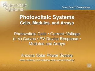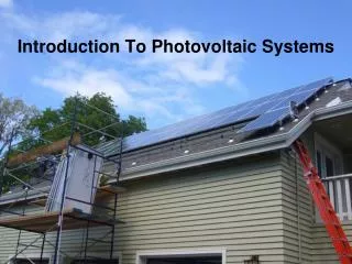
Photovoltaic Systems
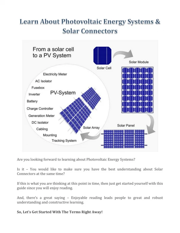
Photovoltaic Systems. Site Surveys and Preplanning. Preliminary Assessment • Site Surveys • Preparing Proposals • Installation Planning Arizona Solar Power Society www.meetup.com/arizona-solar-power-society/. The installer should meet with each customer to discuss available PV system options.

Photovoltaic Systems
E N D
Presentation Transcript
Photovoltaic Systems Site Surveys and Preplanning Preliminary Assessment • Site Surveys • Preparing Proposals • Installation Planning Arizona Solar Power Society www.meetup.com/arizona-solar-power-society/
The installer should meet with each customer to discuss available PV system options.
Information gathered during a site survey should be carefully documented.
Common personal protective equipment (PPE) for preparing and installing PV systems includes head, eye, foot, and fall protection.
Lockout and tagout procedures are important parts of an electrical safety program.
Full-body harnesses connected to a secure safety line system protect a worker from injuries from falling from sloped roofs or roofs with unprotected edges.
Fixed ladders often require cages to prevent workers from falling because the vertical orientation can be difficult to climb.
A sun path calculator is used to evaluate shading at potential array locations.
A variety of testing and measuring devices and marking equipment is used during site surveys.
The density of the module arrangement in an array affects the accessibility and the area required to produce a certain amount of power.
Roof slope is measured with an angle finder or calculated from the rise and run.
A compass is used to determine the orientation of a sloped roof surface.
The potential loss in receivable solar radiation from non-optimal orientations may not be significant.
Magnetic declination varies by location and changes slightly over time. Up-to-date maps are used to determine the necessary adjustment to magnetic compass readings.
Directional bearings from magnetic compasses must be adjusted for magnetic declination.
Shading of PV modules and arrays can cause disproportional reductions in power output.
Most of the daily solar energy is received between 9 AM and 3 PM, so avoiding shading during this period is high priority, especially during the summer.
When the sun is in the northern part of the sky, which can occur at low latitudes during the summer, shading can be caused by obstructions immediately north of an array.
The Solar Pathfinder analyzes shading for potential array locations by comparing the reflections of potential obstructions on the horizon to a sun path diagram of the solar window.
A permanent record of the shading for a particular location can be traced on the hard copy diagram, or by photographing the reflections, which can then be analyzed by the Solar Pathfinder Assistant software to generate reports.
The Solmetric SunEye is an electronic device that includes an on-board camera with a fish-eye lens for photographing the entire sky and horizon at once.
The SunEye’s on-board software can automatically analyze an all-sky photograph for the obstruction that will shade a location at certain times of the day and year.
The altitude angle is the vertical angle to the top of an obstruction.
Altitude angles can be determined using a transit, a protractor, or by calculations from measurements.
The altitude angle method of shading analysis compares the altitude angle and azimuth angle of potential obstructions to a sun path diagram.
The profile angle is the projection of the solar altitude angle onto an imaginary plane perpendicular to a shading surface. This angle is used to calculate the length of shadows.
Profile angle calculations are particularly useful for arranging arrays consisting of multiple rows of modules installed at a tilt. The calculation determines the minimum row spacing to avoid modules shading each other at certain times of the day.
Roofs should be inspected for signs of deterioration during a site survey.
The thickness of roof decking and covering can be determined by inspecting the edge of the roof under the eaves.
Noticeable dips on roof surfaces may be a sign of underlying structural defects.
Inverters and other system components should be located as close together as possible.
A site layout drawing shows basic building dimensions and locations of major components.
A load analysis is part of an energy audit, which is used to evaluate a customer’s energy use for sizing PV systems utilizing batteries.
Energy-use labels on new appliances include information on energy consumption and operating costs.