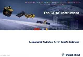
The GRAS Instrument
The GRAS Instrument. C. Marquardt, Y. Andres, A. von Engeln, F. Sancho. GRAS on Metop. Metop-A is the first of three satellites in the European Polar System (EPS) Europe’s contribution to the Initial Joint Polar-Orbiting Operational Satellite System (IJPS)

The GRAS Instrument
E N D
Presentation Transcript
The GRAS Instrument C. Marquardt, Y. Andres, A. von Engeln, F. Sancho
GRAS on Metop • Metop-A is the first of three satellites in the European Polar System (EPS) • Europe’s contribution to the Initial Joint Polar-Orbiting Operational Satellite System (IJPS) • GRAS (GNSS Receiver for Atmospheric Sounding) • 1st custom build GPS receiver for operational RO
GNSS Receiver for Atmospheric Sounding • Build by Saab Space (Sweden; instrument and antennas) and Austrian Aerospace (Austria; S/W, DSP) • Mass ~30kg, power ~40W • ~20MB per orbit / ~280MB per day • First GPS receiver specifically designed for operational radio occultations from space; H/W & S/W design until ~ 2003 (or so) Launched 19th Oct 2006; switched on 27th Oct 2006; worked out of the box.
GRAS Measurement Data • SF/DF and OL/RS tracking: • Code Code phase • Carrier Carrier phase & I’s/Q’s from correlators • Dual frequency channels: • Navigation 8 • Occultation 2 rising & 2 setting • Antenna: • Navigation 10° – 90° elevation • Occultation ± 55° azimuth, beam shaped • Sampling rates: • Navigation SF/DF 3 Hz (1, 3, 10, 25, 50 Hz) • Occultation SF/DF 50 Hz (1, 3, 10, 25, 50 Hz) • Occultation RS 1 kHz (250, 500, 1000 Hz) • Code phase 1 Hz • Onboard navigation 1 Hz
Measurement Modes GRAS measurement modes: • Dual Frequency Carrier Tracking: code and carrier for L1 and L2 are tracked; both (+ C/A) are reported @ 50 Hz • Single Frequency Carrier Tracking: C/A code and carrier phase are tracked; C/A code and carrier are reported @ 50 Hz • Single Frequency Raw Sampling: C/A code tracked, 1 kHz sampling of carrier • SF carrier tracking and raw sampling can occur simultaneously • Either L2 or RS • GRAS uses a geometrical doppler model when in raw sampling: • Implemented as lookup table in the receiver (~ 10 Hz) • Transparent to the user / in the measurement reconstruction • Tracking state information available
Tracking States (cont’d) • Settable parameters: with default values given in SLTA (and RTH) • Rising:SLTA_V = -140 km (0 km)(start C/A acquisition) • SLTA_L2 = -35 km (5 km)(start L2 acquisition) • SLTA_A = 0 km(delay L2 acquisition) • Setting:SLTA_AV = -140 km (0 km)(release SV) • (courtesy Saab)
Tracking States Sample (Setting) • C/A SF I’s and Q’s • Dual I-branch due to navigation message (is usually removed via sign(I)) DF SF RS
Tracking States Sample (Setting, cont’d) • C/A SF I’s and Q’s • Tracking states and actual data highly consistent! DF SF RS L1 carrier lock check
Tracking States Sample (Setting, cont’d) • C/A RS I’s and Q’s • Tracking states also consistent with raw sampling data DF SF RS L1 carrier lock check
Tracking States Sample (Rising) DF SF RS
Tracking States (cont’d) • Tracking states • highly useful for pre-selecting data in both closed and raw sampling measurement modes • much better than heuristic algorithms based on, e.g., SNR thresholds used for other receivers’ data • Other useful information provided by the receiver: • digital and analogue gain changes • noise levels • Overall, we have a much better view on what the receiver is doing compared to pre-GRAS instruments, which is highly appreciated
Instrument Characterisation – Electronic Units • both delays and signal gains available – used for, e.g., estimation of inter-channel biases and (if desired) absolute amplitude calibration • for GRAS, only pseudo ranges are affected by instrument delays
Instrument Characterisation - Antennas • amplitude patterns for the rising antenna • rectangle denotes elevation and azimuth range relevant for occultation measurements
Instrument Characterisation - Antennas • phase patterns for the rising antenna • rectangle denotes elevation and azimuth range relevant for occultation measurements
Instrument Characterisation – Antennas (cont’d) • phase patterns for the zenith antenna • represents double patch antenna design
Instrument Characterisation (cont’d) • GRAS has been characterized on ground before launch • Some parameters are required in measurement reconstruction: • zenith antenna patterns (~ 20 cm along track error in POD if not used) • code delays (large inter-channel biases in pseudoranges if not used) • antenna positions (systematic biases in bending angles if not used) • Others provide additional refinement of reconstructed measurements: • occultation antenna patterns (for ‘absolute’ amplitudes) • temperature dependencies of the above (weak)
Operational Aspects / Anomalies • Buffer overflow on rare occasions (5 times since launch); a threshold parameter needed to be adapted via firmware patch • Single event of simultaneous tracking loss on the zenith channels; receiver recovered after a few seconds (SAA) • GPS SV selection for onboard POD based on GPS Almanachs instead of Ephemerides; • occasional degradation of onboard navigation solution • single event divergence of the onboard POD; required navigation solution reset from the ground
Conclusions • GRAS has been performing excellently since Metop’s launch • No major anomalies • Only a single firmware update so far (and none foreseen) to fix a parameter setting • We’re now beginning to explore the raw sampling data • Prototyping of processing and science algorithms over the next few months (w/ DMI & the GRAS SAF, University of Graz, RUAG/Saab) • Will become operational in <= 1 year from now (we hope) • Test data will be available earlier • Data reconstruction and processing algorithms to be OSS