
Efficient Cellular Network Design Inspired by Bee's Honeycomb Structure
Cellular networks mimic honeycomb design with hexagon-shaped sections, optimizing frequency spectrum use. Towers house BTS equipment converting signals for PSTN. Reliable power setup ensures uptime during outages. TDMA technology and cell phone components explained. MTSO connects cellular regions using carrier's network.

Efficient Cellular Network Design Inspired by Bee's Honeycomb Structure
E N D
Presentation Transcript
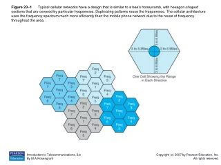
Figure 23–1 Typical cellular networks have a design that is similar to a bee’s honeycomb, with hexagon-shaped sections that are covered by particular frequencies. Duplicating patterns reuse the frequencies. The cellular architecture uses the frequency spectrum much more efficiently than the mobile phone network due to the reuse of frequency throughout the area.
Figure 23–2 Cellular towers are one part of the base transceiver station (BTS) and have specific placement in relation to one another. (Photo courtesy of M. A. Rosengrant)
Figure 23–3 The BTS houses equipment that is able to convert incoming radio frequency signals into electrical ones and zeros that are transported out to the PSTN via T1 circuits.
Figure 23–4 Powering cell sites becomes one of the critical engineering tasks for a cellular engineer. Power is normally set up as shown. Commercial power feeds the site during normal operation. During a commercial power outage, backup batteries kick in and provide power to the equipment. Within a few seconds, the backup generator initiates and takes over as the power source. The process ensures constant uptime during a power outage.
Figure 23–5 The two types of TDMA technology widely deployed in the United States and Europe have different frame structures. (a) The D-AMPS uses a three channel per frame structure. (b) The GSM is built around an eight channel per frame structure.
Figure 23–6 (a) A typical cell phone showing the four main components—antenna, receiver, touchtone pad, and transmitter. (b) A logical view of the components contained in a cell phone.
Figure 23–6 (continued) (a) A typical cell phone showing the four main components—antenna, receiver, touchtone pad, and transmitter. (b) A logical view of the components contained in a cell phone.
Figure 23–7 Cellular regions connect by tying the various MTSOs together using a carrier’s network. The circuits range from T1 up to large OC-3 and OC-12 links.
Figure 23–8 The MTSO is the switch center for the regional cellular network. It looks very much like a typical local central office. A class 5 switch, multiplexers, and backup power reside at the site. The main difference is that the MTSO does not have a large MDF with wire pairs feeding subscribers. The medium to the subscriber is through the air.
