
Calibration and Inversion for Geophysics Problems: A Novel Shape-Based Approach
This research focuses on validating a forward modeling method for geophysics problems. Calibration of soil parameters and shape-based inversion are key components. Experimental verification and localization of objects in the subsurface are conducted using the developed method. The analytical model is applied to cross-well radar (CWR) sensing in half-space media, with a focus on detecting dense non-aqueous phase liquid (DNAPL) contaminations in soil. The inversion technique minimizes the misfit between simulations and observations to reconstruct objects accurately. The study includes calibration experiments, analysis of parameter variances with frequency, and optimization strategies.

Calibration and Inversion for Geophysics Problems: A Novel Shape-Based Approach
E N D
Presentation Transcript
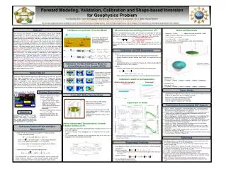
Air Forward Modeling, Validation, Calibration and Shape-based Inversion for Geophysics Problem He (Sophia) Zhan, Carey M. Rappaport, Mohammad Farid, Akram N. Alshawabkeh, Eric L. Miller, Harold Raemer Department of Electrical Engineering, Northeastern University, MA 02115 This work was supported in part by CenSSIS, the Center for Subsurface Sensing and Imaging systems, under the Engineering Research Centers Program of the National Science Foundation (Award Number EEC- 9986821) 0 For 0(’ - j/0) Transmitter For Soil Receiver position The three cascaded two-port junctions with unknowns is matching to the one two-port junction obtained via experiments. Since the soil is lossy, the reflection coefficient at soil junction can be neglected. The magnitude of CTF is solved as: S21 = Transmission measurements S11 = Reflection measurements 0(f) = phase offset The assumption in solving the CTF could affect the phase of the CTF, a progression analysis is conducted to find the appropriate offset amount to the phase. where is the wave number; is the complex permittivity and is the complex permeability; is the source. Relative dielectric constant Loss target Bio - Med Enviro - Civil L3 L3 S5 S4 S1 S3 S2 Validating Validating L2 L2 TestBEDs TestBEDs R2 Fundamental Fundamental Science Science L1 L1 R3 R1 • Pilot-scale (1/100) of CWR imaging • 8 transmitters / 8 receivers • Positioned on a circle of radius 6” • Antenna specifically developed for CWR • Good wideband (0.5 ~ 2.2GHz) coupling to dry/wet sand • Fabricated for repeated insertion in PVC boreholes Depth of T/R is 9”/13” T/R Separation is 8.5” T/R Separation is 12” Depth of T/R is 13”/13” • Network analyzer measurements • Half-Space Lossy Green’s Function, initial soil calibration • Optimal soil selection Abstract Numerical Experiment Half-Space Lossy Green’s Function Model Microwave junction matching method for CTF • frequency = 1.5GHz ; • Additive Gaussian noise SNR = 20dB • Region of interest is 9cm x 9cm x 0.75cm (15x15x15) • x = y 6mm ; z 0.5mm • ’sand = 20 – 0.14j•’obj = 2.6 – 0.001j • Linear array of T/R -- 7 vertical locations and 4 corner positioning • Levenberg-Marquardt method The sensing and detection of dense non-aqueous phase liquid (DNAPL) contaminations in soil has significant geo-environmental benefits; and it is challenging because the background media is uncertain, wave characteristics of media may be hard to determine, and wave scattering of non-ideal volumes in non-uniform backgrounds is difficult. Sensing the subsurface volume between boreholes using cross-well radar (CWR) is less expensive and saves effort, but has not been investigated satisfactorily. In this work, we developed an analytical model to approximate CWR sensing in infinite half-space lossy media in frequency domain. Half-space dyadic Green's function due to a vertical polarized dipole source is introduced. Integration for angles gets far into evanescent range. Born approximation is employed as a linear model for a shape-based inversion that is developed to localize the objectassuming its contrast to the lossy background is a priori information. This forward model is validated via CWR experiment. Soil parameters (relative dielectric constant and loss tangent) variance with frequency is represented by a quadratic polynomial. Calibration for soil parameters is conducted with CWR data using an iterative low-order parameterized optimization technique involving both magnitude and phase information. The validated forward model can predict for CWR sensing experiments in a broad frequency range very well. Localization and reconstruction of the object is performed as a non-linear least square optimization problem by minimizing a cost function that calculates the misfit between the predicted numerical simulation and experimental observation. The proposed inversion method is validated by numerical experiments, and it gives promising preliminary results. • Plane wave decomposition • Fresnel reflection for each plane wave at interface • Integration for angles far into evanescent range Calibration via CWR Experiments • Analysis • Loss tangent variance will only affect the magnitude of the electric field • Relative dielectric constant change affects both the magnitude and the phase • Assumptions • Quadratic polynomial as a function of frequency is sufficient to describe the parameter variances with frequency • Approach • Minimize a cost function in the sense of nonlinear least square error • Obtain optimal polynomial coefficients using Lavenberg-Marquardt Method Validation: Air/Sand Half-Space Model vs. Finite Difference Freq. Domain (FDFD) Initial guess volume Reconstructed volume |Ex| |Ey| |Ez| Half space State of the Art Source depth is 20 below interface in z-direction and centered in xy plane; observation plane is 20 apart from source, where at f=1GHz; The relative dielectric of the lossy media is where There are different detection techniques implemented in the field, such as Direct Push Probe Technologies (DPT), In-Situ Tracers (IST), Geophysical Methods (GM). GM methods are the most non-invasive ones to locate subsurface DNAPLs; avoiding the risk of additional vertical migration of pooled DNAPL. Of course, GPR is the least non-invasive, but has depth limitation. Thus, CWR has been chosen to study in this research. The prospective algorithms in solving the pool characterization problem are based upon multi-scale image formation and shape-based inversion methods for localizing parameterized pollution pools. Ground truth: [xo,yo,zo, lx, ly, lz] = [4.764452 4.764452 0.400000 4.168896 4.1688960 0.2500000]cm Estimated result: [xo,yo,zo, lx, ly, lz] = [4.764460 4.764484 0.400014 4.168896 4.1688959 0.2500099]cm Calibration results for soil parameters FDFD % error Future Works Problem Description Value added to CenSSIS • Segmentation of region of interest with non-uniform voxel to better match the shape of the object while preserving good resolution • Experiment vs. model comparison with DNAPL • Inversion using multi-frequency information • Inversion algorithm validation with CWR data Cross-Well Radar Sensing Setup • Dense non-aqueous phase liquid (DNAPL) contaminants • 0 (2.6 – 0.001j) • Object is wide and thin (pool) • Side width to thickness ration is bigger than 10 typically • relative dielectric constant and loss tangent) are frequency dependent • Saturated sandy soil (lossy medium) • 0 (21 – 0.08j) • Reconstruct and detect the location and the size of the anomaly Experiment vs. Model Publications Acknowledging NSF Support 1) Zhan, H., Farid, M., Rappaport, C. M and Alshawabkeh, A. N., “ Born Approximation Modeling of Lossy Soil Half-Spaces for Cross-Well Radar Sensing of Contaminants with Low-Order Parameter Optimization”, in submission 2) Farid, M. , Zhan, H., Alshawabkeh, A. N, and Rappaport, C. M., “Cross Well Radar : II – Comparison and Validation of Experimentation and Modeling Validation using Channel Transfer Function”, in submission 3) Zhan, H., Rappaport, C., Farid, M., Akram, A. and Raemer, H., “Lossy Halfspace Born Approximation Modeling of Electromagnetic Wave Source and Scattering in Soil by Cross Well Radar”, ASCE Geo-frontiers, Austin, TX, Jan. 2005, electronic CD 4) Farid, M., Akram, A., Zhan, H. and Rappaport, C., “Challenges and Validation of Cross Tomography Experimentation for Inverse Scattering Problems in Soil”, ASCE Geo-frontiers, Austin, TX, Jan. 2005, electronic CD 5) Farid, M. et al. (2003), "Experimental DNAPL Detection Using Cross-Well Radar", SAGEEP, San Antonio, TX. USA, Electronic Proceeding 6) Farid, M. et al. (2003), "Modeling Borehole Dipole Antenna Patterns for Cross-Well Radar DNAPL Imaging", Soil-Rock Conference, MIT, Boston, MA. USA, proceeding, pp. 261-267 7) Farid M. et al. (2002), "DNAPL Detection Using Cross-Well Radar", Environmental Geotechnics, 4th ICEG, pp. 465-470 8) M. Farid, A. Alshawabkeh, C. Rappaport (2003) “Experimental DNAPL Detection Using Cross-Well Radar", SAGEEP, St. Antonio, TX. Objective Develop and verify innovative computational tools for real time efficient, non-invasive, cost-effective and reliable monitoring, delineation and characterization of DNAPLs using Ultra-Wideband Cross-Well Radar. Sensor Independent Transformation: Channel Transfer Function (CTF) Half-space Scattered Field with Born Approximation • In cross-well-radar experiment, coupling between monopole antenna and soil varies with frequency • In forward modeling, wave propagation that is independent of the sensor is studied • CTF is introduced to translate the real experimental data to the form that is compatible to the simulation by forward model • Electric field for 3D electromagnetic problems in frequency domain • vector Helmholtz equation • Assumption: object and homogeneous background are additive • Scattered E-field with first order Born Approximation References 1) M. L. Brewster and A. P. Annan, “GPR Monitoring of a Controlled NAPLRelease: 200 MHZ Radar”, Geophysics, Vol. 59, No. 8, August 1994 2) L. Tsang, J.A. Kong and R. R. Shin, “Theory of Microwave Remote Sensing”, JOHN WILEY & SONS, 1985 3) C. Balanis, “Antenna Theory: Analysis and Design”, Harper & Row, 1982 4) J. Hipp, “Soil Electromagnetic Parameters as Functions of Frequency, Soil Density, and Soil Moisture”, Proc IEEE, Vol. 62, pp. 98-103, Jan. 1974. 5) C. R. Vogel, “Computational Methods for Inverse Problems”,SIAM,2002 6) R. E. Collin, “Foundations for Microwave Engineering”,2nd ed., 1992 7) Misha E. Kilmer, Eric L. Miller, Alethea Barbaro and David Boas, “Three-dimensional shped-based imaging of aborpton perturbation for diffuse optical tomography”, Applied Optics (2003), 42, 3129 – 3144 8) Basak, U. Karbeyaz, “Reduced Complexity Geometry-Based Born Inversion for Frequency Domain Ultrasonic Monitoring of Cancer Treatment”, Ph.D thesis, Sept., 2005 Shape-based Inversion • Find a geometry function such that the voxels have value 1 inside the ellipsoid, 0 elsewhere [8] • Ellipsoid formulation • Entries of diagonal matrix D are the inverse of the lengths of the semi-axes (lx,lyand lz) • Geometry function • Use Levenberg-Marquardt Method • Compute Jacobian matrix analytically The scattered field as a function of source location, receiver location and source frequency, involves a sensor transfer function (dyadic Green’s function and background field ) and the perturbation of object function.


