Download

1 / 116
1.23k likes | 1.5k Vues
This chapter covers the basic concepts of different types of water pumps used in civil engineering, including centrifugal, axial-flow, screw, and reciprocating pumps. It discusses pump classification, components, and hydraulic analysis of pumps and piping systems. Learn about the theory, design, and operation of water pumps in this comprehensive study.

E N D
The Islamic University of GazaFaculty of EngineeringCivil Engineering DepartmentHydraulics - ECIV 3322 Chapter 5 Water Pumps
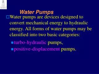
Definition • Water pumps are devices designed to convert mechanical energy to hydraulic energy. • They are used to move water from lower points to higher points with a required discharge and pressure head. • This chapter will deal with the basic hydraulic concepts of water pumps
Pump Classification • Turbo-hydraulic (kinetic) pumps • Centrifugal pumps (radial-flow pumps) • Propeller pumps (axial-flow pumps) • Jet pumps (mixed-flow pumps) • Positive-displacement pumps • Screw pumps • Reciprocating pumps
This classification is based on the way by which the water leaves the rotating part of the pump. • In radial-flow pump the water leaves the impeller in radial direction, • while in the axial-flow pump the water leaves the propeller in the axial direction. • In the mixed-flow pump the water leaves the impeller in an inclined direction having both radial and axial components
Schematic diagram of axial-flow pump arranged in vertical operation
Screw pumps. • In the screw pump a revolving shaft fitted with blades rotates in an inclined trough and pushes the water up the trough.
Reciprocating pumps. • In the reciprocating pump a piston sucks the fluid into a cylinder then pushes it up causing the water to rise.
Centrifugal Pumps • Demour’s centrifugal pump - 1730 • Theory • conservation of angular momentum • conversion of kinetic energy to potential energy • Pump components • rotating element - impeller • encloses the rotating element and seals the pressurized liquid inside – casing or housing
Centrifugal Pumps • Broad range of applicable flows and heads • Higher heads can be achieved by increasing the diameter or the rotational speed of the impeller Flow Expansion Discharge Casing Suction Eye Impeller Impeller Vanes
Centrifugal Pump: • Centrifugal pumps (radial-flow pumps) are the most used pumps for hydraulic purposes. For this reason, their hydraulics will be studied in the following sections.
Main Parts of Centrifugal Pumps • Impeller: • which is the rotating part of the centrifugal pump. • It consists of a series of backwards curved vanes (blades). • The impeller is driven by a shaft which is connected to the shaft of an electric motor.
Main Parts of Centrifugal Pumps • Casing • Which is an air-tight passage surrounding the impeller • designed to direct the liquid to the impeller and lead it away • Volute casing. It is of spiral type in which the area of the flow increases gradually.
Suction Pipe. • Delivery Pipe. • The Shaft: which is the bar by which the power is transmitted from the motor drive to the impeller. • The driving motor: which is responsible for rotating the shaft. It can be mounted directly on the pump, above it, or adjacent to it.
Note that a centrifugal pump can be either submersible (wet) or dry.
Hydraulic Analysis of Pumps and Piping Systems • Pump can be placed in two possible position in reference to the water levels in the reservoirs. • We begin our study by defining all the different terms used to describe the pump performance in the piping system.
The following terms can be defined • hs(static suction head): it is the difference in elevation between the suction liquid level and the centerline of the pump impeller. • hd(static discharge head): it is the difference in elevation between the discharge liquid level and the centerline of the pump impeller. • Hstat(static head): it is the difference (or sum) in elevation between the static discharge and the static suction heads:
Hms(manometric suction head): it is the suction gage reading (if a manometer is installed just at the inlet of the pump, then Hms is the height to which the water will rise in the manometer). • Hmd(manometric discharge head): it is the discharge gage reading (if a manometer is installed just at the outlet of the pump, then Hmd is the height to which the water will rise in the manometer). • Hm(manometric head): it is the increase of pressure head generated by the pump:
Ht(total dynamic head): it is the total head delivered by the pump: Case 1 Eq.(1) Case 2 Eq.(2)
Htcan be written in another form as follows: Case 1 Case 2 Substitute ino eq. (1) but Eq.(3) Case 1
Equation (3) can be applied to Case 2 with the exception that : In the above equations; we define: hfs: is the friction losses in the suction pipe. hfd: is the friction losses in the discharge (delivery) pipe. hms: is the minor losses in the suction pipe. hmd: is the minor losses in the discharge (delivery) pipe.
Pump Efficiency or Which is the power input delivered from the motor to the impeller of the pump.
Motor efficiency : which is the power input delivered to the motor. Overall efficiency of the motor-pump system:
Cavitation of Pumps and NPSH • In general, cavitation occurs when the liquid pressure at a given location is reduced to the vapor pressure of the liquid. • For a piping system that includes a pump, cavitation occurs when the absolute pressure at the inlet falls below the vapor pressure of the water. • This phenomenon may occur at the inlet to a pump and on the impeller blades, particularly if the pump is mounted above the level in the suction reservoir.
Under this condition, vapor bubbles form (water starts to boil) at the impeller inlet and when these bubbles are carried into a zone of higher pressure, they collapse abruptly and hit the vanes of the impeller (near the tips of the impeller vanes). causing: • Damage to the pump (pump impeller) • Violet vibrations (and noise). • Reduce pump capacity. • Reduce pump efficiency
How we avoid Cavitation ?? • To avoid cavitation, the pressure head at the inlet should not fall below a certain minimum which is influenced by the further reduction in pressure within the pump impeller. • To accomplish this, we use the difference between the total head at the inlet , and the water vapor pressure head
Where we take the datum through the centerline of the pump impeller inlet (eye). This difference is called the Net Positive Suction Head (NPSH), so that There are two values of NPSH of interest. The first is the required NPSH, denoted (NPSH)R , that must be maintained or exceeded so that cavitation will not occur and usually determined experimentally and provided by the manufacturer. The second value for NPSH of concern is the available NPSH, denoted (NPSH)A , which represents the head that actually occurs for the particular piping system. This value can be determined experimentally, or calculated if the system parameters are known.
How we avoid Cavitation ?? • For proper pump operation (no cavitation) : (NPSH)A > (NPSH)R
Determination of (NPSH)A datum hs applying the energy equation between point (1) and (2), datum at pump center line
Note that (+) is used if hs is above the pump centerline (datum).
Thoma’s cavitation constant The cavitation constant:is the ratio of (NPSH)R to the total dynamic head (Ht) is known as the Thoma’s cavitation constant ( ) Note: If the cavitation constant is given, we can find the maximum allowable elevation of the pump inlet (eye) above the surface of the supply (suction) reservoir.
Selection of A Pump It has been seen that the efficiency of a pump depends on the discharge, head, and power requirement of the pump. The approximate ranges of application of each type of pump are indicated in the following Figure.
Selection of A Pump • In selecting a particular pump for a given system: • The design conditions are specified and a pump is selected for the range of applications. • A system characteristic curve (H-Q) is then prepared. • The H-Q curve is then matched to the pump characteristics chart which is provided by the manufacturer. • The matching point (operating point) indicates the actual working conditions.
System Characteristic Curve • The total head, Ht, that the pump delivers includes the elevation head and the head losses incurred in the system. The friction loss and other minor losses in the pipeline depend on the velocity of the water in the pipe, and hence the total head loss can be related to the discharge rate • For a given pipeline system (including a pump or a group of pumps), a unique system head-capacity (H-Q) curve can be plotted. This curve is usually referred to as a system characteristic curve or simply system curve. It is a graphic representation of the system head and is developed by plotting the total head, over a range of flow rates starting from zero to the maximum expected value of Q.
System with valve partially closed 120 100 systemcurve 80 60 Head (m) 40 Static head (z2-z1) 20 0 0 0.2 0.4 0.6 0.8 Discharge (m3/s)
Pump Characteristic Curves • Pump manufacturers provide information on the performance of their pumps in the form of curves, commonly called pump characteristic curves (or simply pump curves). • In pump curves the following information may be given: • the discharge on the x-axis, • the head on the left y-axis, • the pump power input on the right y-axis, • the pump efficiency as a percentage, • the speed of the pump (rpm = revolutions/min). • the NPSH of the pump.