Download
1 / 23
230 likes | 258 Vues
If you want to know about Concrete Wall System, then visit our website. We provide information about the concrete wall system and also provide you the best concrete wall system. For more information visit http://www.dincel.com.au

E N D
C CO ON NC CR RE ET TE E W WA AL LL LS S W WI IT TH H P PE ER RM MA AN NE EN NT T F FO OR RM MW WO OR RK K H HA AV VI IN NG G F FI IB BR RE E- -C CE EM ME EN NT T S SH HE EE ET TS S ( (O OR R S SI IM MI IL LA AR R) ) O ON N B BO OT TH H F FA AC CE ES S DISCLAIMER The information contained in this document is intended for the use of suitably qualified and experienced engineers. This information is not intended to replace design calculations or analysis normally associated with the design and specification of buildings and their components. Dincel Construction System Pty Ltd accepts no liability for any circumstances arising from the failure of a specifier or user of any part of Dincel Construction System to obtain appropriate professional advice about its use and installation or from failure to adhere to the requirements of appropriate Standards and Codes of Practice, and relevant Building Codes. Page 1 of 23
C CO ON NT TE EN NT TS S P PE ER RM MA AN NE EN NT T C CO ON NC CR RE ET TE E ( (A A) ) A AR RE E F FO OR RM MW F FI IB BR RE E- -C CE EM ME EN NT T WO OR RK K P PU UR RP PO OS SE ES S? ? S SH HE EE ET TS S S SU UI IT TA AB BL LE E F FO OR R WA AL LL LS S ( (B B) ) ( (C C) ) C CO OM MP PA AR RI IS SO ON N T TA AB BL LE E – – D DI IN NC CE EL L V VS S F FC C W E EX XP PL LA AN NA AT TI IO ON N O OF F C CO OM MP PA AR RI IS SO ON N T TA AB BL LE E (1) AS3600 – SECTION 4, STRUCTURAL ENGINEERING – DURABILITY COMPLIANCE C CO ON NT TR RO OL L O OF F M MO OI IS ST TU UR RE E F FL LO OW W ( (2 2) ) ( (3 3) ) T TH HE ER RM MA AL L B BR RI ID DG GI IN NG G ( (4 4) ) V VA AP PO OU UR R B BA AR RR RI IE ER RS S S ST TR RU UC CT TU UR RA AL L E EN NG GI IN NE EE ER RI IN NG G – – F FI IR RE E C CE ER RT TI IF FI IC CA AT TI IO ON N O OF F F FC C W WA AL LL LS S ( (5 5) ) (6) SAFETY ISSUE DUE TODELAMINATION OF FIBRE-CEMENT SHEETS B BU UI IL LD DA AB BI IL LI IT TY Y A AN ND D S SA AF FE ET TY Y ( (7 7) ) ( (8 8) ) ( (9 9) ) W WA AL LL L F FO OR RM MW WO OR RK K C CO ON NC CR RE ET TE E U US SE E ( (1 10 0) ) S ST TE EE EL L R RE EI IN NF FO OR RC CE EM ME EN NT T U US SE E ( (1 11 1) ) E EN NV VI IR RO ON NM ME EN NT TA AL L I IM MP PA AC CT TS S ( (1 12 2) ) A AC CO OU US ST TI IC CS S A AR RE E M MA AG GN NE ES SI IU UM M O OX XI ID DE E B BO OA AR RD DS S S SU UI IT TA AB BL LE E F FO OR R P PE ER RM MA AN NE EN NT T C CO ON NC CR RE ET TE E F FO OR RM MW WO OR RK K P PU UR RP PO OS SE ES S? ? ( (D D) ) Page 2 of 23
( (A A) ) A AR RE E F FI IB BR RE E- -C CE EM ME EN NT T S SH HE EE ET TS S S SU UI IT TA AB BL LE E F FO OR R P PE ER RM MA AN NE EN NT T C CO ON NC CR RE ET TE E F FO OR RM MW WO OR RK K P PU UR RP PO OS SE ES S? ? NO.Fibre-cement sheets are developed for the cladding of dry wall construction. Fibre-cement sheets are not suitable for concrete formwork purposes. (download) Leaky Buildings – Are Fibre-Cement Sheets Suitable ( (B B) ) C CO OM MP PA AR RI IS SO ON N T TA AB BL LE E – – D DI IN NC CE EL L V VS S F FC C W C CO ON NC CR RE ET TE E W WA AL LL LS S W WI IT TH H P PE ER RM MA AN NE EN NT T F FO OR RM MW B BU UI IL LD DI IN NG G A AU UT TH HO OR RI IT TY Y C CO OM MP PL LI IA AN NC CE E I IS SS SU UE ES S A AN ND D C CO OM MP PA AR RI IS SO ON NS S The system matching the above description consists of metal studs of ‘C’ shaped forms at close centres to hold the fibre cement sheets at both faces by means of glue as a formwork for concrete infill. The generic names of these walls are called FC Walls in the following table. The below table is a comparison between Dincel and FC Walls and also highlights some possible non-compliance issues (refer chapters following the below table) which includes the following for: • Structural Design Engineers: Item (C) (5) Structural Capacity. WA AL LL LS S WO OR RK K Item (C) (1) Durability. Item (C) (8) Voids in concrete walls. • Builder: Item (C) (6) Delamination of fibre-cement sheets. Items (2) and (3) The requirement of cavity façade walls. Leaky Building Syndrome. • Principal Certifier: Acceptance of the above items. I IS SS SU UE E D DI IN NC CE EL L W WA AL LL L F FC C W WA AL LL L YES. The Dincel polymer perfectly suits as a formwork, cannot be damaged by water alkaline conditions and eliminates problem. Except one supervisor. NIL skilled labour required. NO. Fibre-cement sheets are not suitable when used in contact with water – high alkaline conditions (download – Leaky Buildings) cause honeycombing, air voids, etc. YES. Specialist team required. S Su ui it ta ab bi il li it ty y f fo or r C Co on nc cr re et te e F Fo or rm mw wo or rk k ✔ ✔ ✘ ✘ honeycombing S Sk ki il ll le ed d L La ab bo ou ur r ✔ ✔ ✘ ✘ Page 3 of 23
I IS SS SU UE E D DI IN NC CE EL L W WA AL LL L F FC C W WA AL LL L YES. 13 kg/m2, typical panel (0.33m wide), of 3m high is 13 kg. NO. Average 33 kg/m2, typical panel (1.2m wide) of 3m high is 118 kg. IMPORTANT: The Worker Safety & Health Act 2011 requires that each of these panels must be installed by cranes. No manual lifting heavier than average 20kg/man is allowed. Closely placed bracing required in each application. L Li ig gh ht tw we ei ig gh ht t ✔ ✔ ✘ ✘ NIL required when associated with conventional floor formwork. B Br ra ac ci in ng g f fo or r I In ns st ta al ll la at ti io on n ✔ ✔ ✔ ✔ ✘ ✘ ✘ ✘ Safe 18m2/man/hour. (Download) Dincel “Solution for Construction Safety” for lifting limits under the Worker Safety & Health Act 2011. •Lighter – this allows Dincel and conventional floor formwork to be installed on Day 1. •Elimination of wall bracing and joints. •Water and electrical reticulation can be done at any time and eliminates the critical path for the coordination of three trades. •Dincel is not affected by wet weather conditions. Dincel Wall does not require wall joints. Walls already built up to 140m long without joints. YES. Dincel is certified by CSIRO under 6m head of water pressure. Dincel is currently used even for water tanks. YES. Dincel has vapour barriers on both faces. It is a BCA requirement that façade walls have vapour barriers on the warm face of the wall (i.e. both sides in all except for tropical climates). NO. The net concrete thickness between the Dincel service spacers is 150mm hence complies with the BCA’s deemed-to-satisfy condition. Claimed speed of installation is 100m2/day for 3 men, for 8 hours a day: 4.2m2/man/hour. •Heavy panels require the walls to be installed (utilising diagonal wall bracings) installation of conventional floor formwork. In comparison to Dincel, this additional loss of time. •Under wet weather conditions fibre-cement sheets lose their strength significantly which may result in either bulging or blow- out of the formwork. FC Walls are required to have joints at 5m to 8m centres. F Fa as st te er r speed of installation is before the is significant W Wa al ll l J Jo oi in nt ts s ✔ ✔ ✘ ✘ W Wa at te er rp pr ro oo of f NO. FC Walls are NOT waterproof. Fibre-cement sheets cannot be used in contact with water. ✔ ✔ ✘ ✘ ✘ ✘ NO. FC Walls require vapour barriers. V Va ap po ou ur r B Ba ar rr ri ie er r ✔ ✔ W Wo ou ul ld d t th he e p pr re es se en nc ce e o of f s se er rv vi ic ce e r re et ti ic cu ul la at ti io on n c ca au us se e a ac co ou us st ti ic c c co om mp pl li ia an nc ce e p pr ro ob bl le em ms s YES. The BCA acoustic deemed- to-satisfy compliance is minimum net concrete thickness of 150mm thick concrete. Services must not reduce this thickness at any point. Refer Item (12) following this table. ✔ ✔ ✘ ✘ Page 4 of 23
I IS SS SU UE E D DI IN NC CE EL L W WA AL LL L F FC C W WA AL LL L YES. Can be installed even after wall concrete filling because of inbuilt service spacers. This eliminates the critical path between the plumbing, electrical and wall installation trades. •Dincel complies with the “deemed to satisfy” conditions of AS3600 and other international concrete structures codes such as ACI 318 and EuroCode. This gives Dincel the design capacities allowed by the concrete codes. NO. Placed prior to concrete filling which causes further delay for concrete pouring service reticulation. E El le ec ct tr ri ic ca al l a an nd d W Wa at te er r R Re et ti ic cu ul la at ti io on n ✔ ✔ ✘ ✘ because of •“FC Wall is an alternative solution” in which its load capacity is limited to its fire testing report. Refer Item (5) – Structural Engineering Certificate chapter following this table. •As explained in the following document Item No: (7) FC Wall does NOT comply with AS3600 – Section (3) – durability requirement. Refer to the document following this table for the quoted item numbers. •Delamination of fibre-cement sheets – Item (6). •Potential corrosion of metal studs – Item (7). •The use of single skin façade wall items (2) and (3). •Undetected voids in concrete leading to non-compliance for structural strength, fire and acoustics – Item (9). •FC Walls horizontal and vertical steel. •FC Walls’ fire certificate states that minimum concrete strength is 32 Mpa. •Honeycombing and air pockets are commonly observed. •FC Wall is a significant CO2 producer because of its metal studs. •FC Walls’ fire certification limits its use to 32 Mpa. S St tr ru uc ct tu ur ra al l C Co om mp pl li ia an nc ce e ✔ ✔ ✘ ✘ Fire NIL N No on n B BC CA A C Co om mp pl li ia an nc ce e ✔ ✔ ✘ ✘ •Dincel can be used with no vertical or horizontal steel for walls subject to axial compression. Basement walls only require vertical steel bars. •20 Mpa or even lower concrete strength can be used. •Honeycombing cannot happen. •Dincel mainly uses no steel which is the main CO2 producer. •Dincel has been used with 50% less cement and still achieved 32 Mpa concrete. •AS3600 - minimum 20 Mpa Concrete Durability requirement can be reduced because of Dincel’s waterproof formwork protection. R Re ei in nf fo or rc ci in ng g s st te ee el l a an nd d c co on nc cr re et te e u us sa ag ge e require both ✔ ✔ ✘ ✘ E En nv vi ir ro on nm C CO O2 2 me en nt t/ / ✔ ✔ ✘ ✘ polymer Page 5 of 23
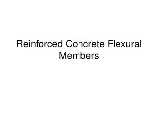
( (C C) ) E EX XP PL LA AN NA AT TI IO ON N O OF F C CO OM MP PA AR RI IS SO ON N T TA AB BL LE E (1) AS3600 – SECTION 4, STRUCTURAL ENGINEERING – DURABILITY COMPLIANCE SYSTEM A CONVENTIONAL REINFORCED CONCRETE WITH REMOVABLE FORMWORK FIGURE 1 SYSTEM – A •Concrete cracking is unavoidable; if the crack width is less than the AS3600 allowance they are self-healed (i.e. crack is closed) because of calcination (i.e. autogenous healing). This way, corrosion of the steel and deterioration of the concrete due to environmental attacks are avoided. SYSTEM – B •MUST HAVE CONCRETE COVER over any metallic component (irrespective of whether metal channels are used for structural purposes or not) TO COMPLY WITH AS3600 – 2009 – Clause 4.10.3.7. •Drying concrete shrinks away from the face of metal channels causing a permanent gap/crack that will allow air, moisture or water to pass through. •The gap between concrete and metal (unless it is concrete to concrete) cannot self-heal. •The gap created leads to corrosion of the steel bars, metal channels and deterioration of concrete. This is why System-B must have adequate concrete cover at each face covering the metal channels as shown above in Detail B. •AS3600 does not accept galvanising or paints, even membranes in lieu of concrete cover. Refer Appendix, Item No: 1, AS3600 commentary by Paul Walsh, CSIRO and AS3600, Table 4.3, Note 9: “protective surface coatings may be taken into account in the assessment of exposure classification”. The minimum AS3600 compliance requirement for the design life of any structural wall is 50 years +/- 20% (AS3600 – Clause 4.1) which is up to 60 years. SYSTEM B PROPRIETARY CONCRETE WALL WITH PERMANENT FIBRE-CEMENT OR MgO SHEET FORMWORK Page 6 of 23
AS3600, Clause 4.10.3.7 compliance for durability purposes cannot be achieved for FC Walls since the metal channels, at their surface, only have 6mm fibre-cement sheet in lieu of the mandatory concrete cover. Inadequate concrete cover at the surface of FC Walls will lead to corrosion of the metal channels which will lead to corrosion related steel expansion and concrete spalling. The only form of protection for the FC Walls at the building façade that is commonly available is the application of an ordinary paint/render finish which is not a membrane system. AS3600 (Concrete Structures Code) Clause 4.3 (refer Appendix – Item 1) does not recognise ordinary paint/render as adequate protection for durability purposes. The recognised protective coatings (i.e. membranes, galvanising) do not provide any concession to avoid minimum concrete cover requirement (refer Appendix – Item 1, AS3600, Table 3, Note: 9) of the Concrete Structures Codes such as AS3600, ACI318 or Eurocode. Further to the above, warranties for membranes and galvanising can only be accepted subject to ongoing maintenance (refer AS3600 – Appendix Items 1 and 2). In the case of the galvanised studs (it must also be considered that light galvanising can easily be damaged by aggregates during the placement of concrete infill; further to this no manufacturer provides a guarantee for 60 years for light galvanising), it should be noted that they are hidden by the glue fixed fibre-cement sheeting, therefore the metallic components cannot be visually inspected and corrosion is therefore allowed to occur behind the fibre-cement sheet with no method of inspection and no method of repair. This does not comply with the ongoing maintenance requirement of AS3600 where protective coatings (galvanising, membranes) are used to reduce minimum concrete cover requirement. The following diagram represents a case where there is not even a paint protection to the FC Walls. CONSTRUCTION AGAINST EXISTING BUILDINGS FIGURE 2 The problems highlighted in this document can be worsened. Walls of a new building of the above diagram having concrete facade walls incorporating fibre-cement sheets as formwork will have no protection offered by external coating systems, particularly when Zones A and B of the above diagram have no adequate access. Page 7 of 23
(2) CONTROL OF MOISTURE FLOW Rain penetration, water diffusion, air leakage and condensation are potential issues that relate to moisture flow within FC-Walls due to their porous nature. Wall systems incorporating porous claddings such as fibre-cement sheets absorb rainwater or water from the concrete mix during construction. This is the reason why buildings experience most condensation/mould/mildew problems within the first 12 months after the buildings’ completion. The absorbed water or moisture remains in the concrete itself, then is released through the porous fibre-cement sheets in the early stages of the building’s life while the walls are still drying. The presence of moisture flow is known to cause paint peeling off, excessive shrinkage resulting in cracking at the fibre-cement sheet joints, mould and mildew problems. This problem is therefore relevant for all internal or façade walls having fibre-cement sheets and concrete infill. For further information (download) – Leaky Buildings – Are Fibre-Cement Sheets Suitable. Applied paint/render systems on FC-Walls cannot stop moisture flow unless they use membrane systems which are required to be maintained on an ongoing basis. The Australian Concrete Structures Standard AS3600 – commentary clause 4.3 (refer Appendix – Item 1) does not recognise common commercially available paint/render systems as protection to walls for durability purposes because the moisture flow due to their porous nature cannot be avoided. FC-Walls are required to have joints. The presence of joints also makes the control of moisture flow nearly impossible unless cavity walls at the facades are provided. Dincel is joint free waterproof wall which does not allow moisture flow. (Download – CSIRO Certificate to see vapour transmission testing and certification). Dincel-Wall is the only waterproof wall as tested and certified by CSIRO (download – Waterproof Walls) – other walls can be made waterproof by application of membrane systems. (3) THERMAL BRIDGING FC-Walls incorporating metal studs joining each face of the wall provides the path for thermal bridging (i.e. energy efficiency, mould/mildew). Walls with thermal bridging will require a well-ventilated and insulated cavity and inner skin wall to avoid condensation/fungus growth. Dincel Wall’s polymer protection avoids thermal bridging. (4) VAPOUR BARRIERS Vapour barriers are required on the warm face of building façade walls. The warm face of the building façade wall can be the internal or external face of single skin FC-Walls depending on the climate. A wall with fibre-cement sheets may consist of externally applied paint/render incorporating a 2mm skim coat to the entire wall’s face, and 2mm skim coat plus painting for the internal face of a façade wall. The definition of the required impervious vapour barrier sheeting will not be satisfied if the applied paint/render system and 2mm skim coat is identified as porous (i.e. not a membrane system) material. As previously highlighted, AS3600 – Commentary Clause 4.3 (refer Appendix – Item 1) states that only membrane type paints (provided ongoing maintenance program is established) are qualified as non-porous, hence can be used as vapour barriers. Page 8 of 23
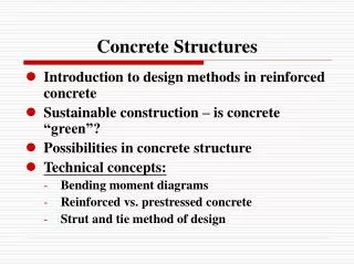
Dincel-Walls’ permanent polymer encapsulation automatically complies with this requirement on both faces of the wall. (Download – CSIRO Certificate. Dincel’s vapour transmission rate is 180 times better than the standard). (5) STRUCTURAL ENGINEERING - FIRE CERTIFICATION OF FC WALLS AS3600 – 2009, Appendix B, states that “alternative solutions” can only be used within the limits of the test reports (i.e. fire, durability, etc.). FC Walls consist of closely spaced metal channels. These metal channels do not have any concrete covers to them. This is why FC Walls are classified as an “alternative solution”. It is important to understand that the prototype adopted by all engineering codes does not consist of metallic components (refer Figure 4) other than steel reinforcement. Therefore, it is the structural engineers’ responsibility to ensure that the FC Walls are designed within the limits of their fire testing certification. It appears that there is a misinterpretation by some structural engineers about the use, limits and applicability of fire test report for FC Walls. It is therefore important to explain the following: (i) The Fire Behaviour of Conventional Concrete Walls This subject is explained by (download) Dincel Solution for Hydro Carbon Fire. However, the fire spalling behaviour of conventional reinforced concrete walls can be summarised as follows: (a) Pore Pressure Spalling (b) (c) Aggregate Expansion Spalling Reinforcing Steel Expansion Spalling If steel reinforcement does not have adequate concrete cover for insulation purposes, the heat quickly reaches the steel. The steel bars expand under the heat of fire causing spalling to concrete. Refer Figure 3 below. FIGURE 3 Page 9 of 23
The Fire Behaviour of FC Walls (ii) The abovementioned conventional concrete behaviour occurs with FC Walls as well. However, FC Walls are potentially subjected to additional concrete spalling for the following reason. Figure 4 below shows a typical FC Wall. The metal channels are closely spaced to each other. The flanges of the metal channels further reduce the clear distance between the channels. The metal channels’ surface coverage is at least 30% at each wall face. The face of the metal channels is covered with 6mm fibre-cement sheets which delaminate and detach from the metal channels in a short space of time (fire tests show that this period is 15 minutes) during a fire event. This results in the metal channels being directly exposed to fire. The exposed (i.e. unprotected) flange of the partially encased metal ‘C’ shape channel, under the fire’s heat, expands and the resultant stress causes “corner spalling” emanating from the face of the metal channel as shown in the figure below. The effect of normal concrete’s spalling behaviour in a fire event is thus further exacerbated by the presence of exposed metal flanges. FIGURE 4 It can be argued that the metal channels of FC Walls are not used for structural purposes. The main issue is to understand that the presence of metal channels contribute to additional spalling in comparison to conventional concrete which is beyond normal concrete structures codes. Concrete structures codes such as AS3600, ACI318 or Eurocode are specifically written for concrete walls without any built in metal channels of Figure 4 above. This additional spalling may cause structural failure, especially in highly stressed FC Walls. Why is Concrete Spalling Important? During a fire event, the structural wall thickness reduces due to concrete spalling as explained above. International engineering codes, including the Australian AS3600, are based on the test results for conventional reinforced concrete walls having adequate cover to steel reinforcements. These tests determine the engineering code recommendations which account for concrete spalling due to pore pressure, aggregate expansion and having adequate cover to the steel. The fundamental difference between FC Walls and conventional concrete walls is the presence of closely spaced metal channels (i.e. 33% of metal coverage of the wall surface) which generates Page 10 of 23
additional concrete spalling in comparison to conventional concrete walls. Additional spalling means reduction in wall thickness during a fire hence reduction in the load carrying capacity. This difference distinguishes FC Walls from conventional reinforced concrete walls. Conventional concrete walls, accepted by the Concrete Structures Code, do not accommodate the metal channels shown in Figure 2. Therefore, FC Walls clearly do not conform with the prototype accepted by the Concrete Structures Codes. This is why FC Walls should not be engineered using AS3600 or a similar engineering code unless FC Walls produce test results above the test criteria shown below. It must be clear to FC Walls specifiers and users that FC Walls must be used within the limits of their fire test certificates. A typical example is as follows: (i) Concrete specification; 32Mpa, 10mm aggregate, 120mm slump. (ii) 200 kN/m maximum load carrying capacity. (iii) 3,000mm maximum wall height. (iv) 136mm net concrete thickness. Concrete spalling in an actual fire or fire test occurs within the first 45 minutes of fire exposure. As a result, the collapse of the wall with excessive spalling can even occur at 30 to 45 minutes of fire exposure if the wall carries a load in excess of 200 kN/m test load. It is therefore essential for all design engineers to limit their design for FC Walls within the above parameters as stated in the CSIRO letter dated 24th August 2006 (copy available upon request). The moisture in the concrete determines the magnitude of concrete spalling. EuroCode hence AS3600 – 2009 adopts the concrete spalling values as less than 3% moisture. (Download) – Compliance of Concrete Mix Specification. No one knows how FC Walls will behave under fire conditions at high load capacities unless they are tested at the level as claimed by FC Walls. Fire testing facilities do not allow more than 300 kN/m load tests. FC Walls tested load capacity is 200 kN/m. Would the presence of metal studs create additional concrete spalling that could lead to structural collapse? (the answer is YES according to known science as unprotected metal expansion causes additional spalling). AS3600-2009, Appendix B states that a product’s performance/compliance if demonstrated by testing, the test loads must represent 100% of the design loads. In other words, FC Walls cannot be used above the test loads of 200kN/m. (6) SAFETY ISSUE DUE TODELAMINATION OF FIBRE-CEMENT SHEETS (i) Under Fire Conditions – BCA Fire Resistance/Stability and Exit Requirements The delamination and detachment of fibre-cement sheets during building façade wall fires, due to their glued attachment to metal channels of FC walls, represents safety liability for by-passers and fire fighters (i.e. detached sheets of say 1.2m x 2.7m can be airborne for significant distances). The following compliance will be relevant to the subject walls: • BCA – 2010 Part C1 – Fire Resistance and Stability Clause C1.12 (f) (ii), (iii) and (iv), and • BCA – 2010 Specification C1.1 Clause 2.4 (a) (i) and (ii). Page 11 of 23
The delamination of the attachments (i.e. fibre-cement sheets), because of adhesives, must comply with Clause C1.12 (f) (ii) and (iii) so that the delaminating fibre-cement sheets does not make the required exit unusable – (BCA Specification C1.1 – Clause 2.4 (a) (ii)). This item in particular must be assessed under the Worker Health & Safety Act 2011. FC Wall’s fire testing clearly states that fibre-cement sheets delaminate after 15 minutes exposure to fire (no glue can resist heat of more than 80°C). The building fire temperature reaches 400°C within 5 minutes and 800°C within 15 minutes in accordance with CSIRO. It is recognised that delamination of fibre-cement sheets occur within 15 minutes of fire testing of FC Walls when the temperature in the furnace reaches about 800°C. There will be no people within the building to be affected from falling fibre-cement sheets at 800°C fire intensity. However, this explanation does not cover the exterior face of façade wall fires. The BCA Clause Specification C1.1 Clause 2.4 (a) (ii) is to eliminate the above or similar incidents. This issue will be particularly important when considering that the fire fighting response time is 20 minutes. Therefore, the delaminated panels will most likely interfere with the actions of the fire fighters. (7)BUILDABILITY (Easier Construction) AND SAFETY Refer (download) Dincel Solution for Construction Safety • Dincel-Forms are lightweight (13kg per 3m length), thus can be easily man handled (no need for on-site cranage). FC-Walls’ typical panel of 1.2 x 3m weighs 118 kg which is clearly beyond the acceptance of Work Safety regulations for manual handling. • Heavy FC-Walls with metal component may represent a potential hand cutting injury during manual handling. • Non-skilled labour use. The FC-Walls are required to be installed and concrete poured by skilled installers. Dincel is the only system that allows installation even by first time users. • Dincel-Walls’ inbuilt service spaces allow water reticulation or power/communication cables to be installed before or after concrete infilling. It allows windows to be installed before or after construction from the inside of the building without the need for scaffolding. The load bearing Dincel-Wall/Column system allows the formworking trades to construct the entire building skeleton without wall bracings (with conventional floor formwork) and without other trades interfering with the formworking trade. This way, the ultimate coordination and sequencing is achieved and no other building trades are on the critical path of the formworking/concreting trades. • FC-Walls are erected using diagonal wall bracing at close centres. This represents a safety issue to the formworking trades installing the floor formworking. However, Dincel is installed by the floor formworking trade without bracings, thus eliminating a very clear safety risk. • Dincel-Forms are assembled by simply snapping the forms to each other which provides unmatchable construction speed, together with the abovementioned issues when compared to FC-Walls. Page 12 of 23
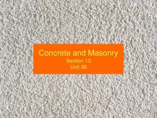
AIR VOIDS CAUSE CORROSION (PHOTOS FROM A BUILDER OF A SYDNEY PROJECT THAT HAS USED FC WALLS) AIR VOIDS IDENTIFIED AND GROUTED BY THE INSTALLER AIR VOIDS FAILED TO BE IDENTIFIED BY THE INSTALLER WHO GROUTED THE ABOVE VOIDS FIBRE CEMENT SHEET JOINT FIBRE CEMENT SHEET REMOVED FOR INSPECTION AIR VOIDS AIR VOIDS GLUE ON METAL CHANNELS Page 13 of 23
(8) WALL FORMWORK Dincel-Form consists of polymer skins which do not allow capillary action between the wet concrete mix and polymer form unlike fibre-cement sheets. No friction can possibly develop in the absence of capillary action, hence honeycombing. Honeycombing is a common problem and is unavoidable with porous formworking materials such as fibre-cement sheets or masonry blocks resulting in voids in concrete walls. These honeycombing voids are potential problems compromising acoustic, fire and structural performance. This is the reason why the installers of FC-Walls are known to tap the face of the concreted walls to look for and fill those voids that they can identify. The ones that are not identified remain with acoustic, fire and structural concerns. The above photo shown on page 13 reveals typical air voids normally experienced by FC Walls. FC-Walls are also known to use very high concrete slumps which require high skilled labour use to avoid bulging/blowouts and naturally will require extended periods of drying time before application of the paint/render finishes if high water/cement ratios are used to achieve high slump. The high slump concrete (i.e. typical block mix, 10mm aggregate, about 200mm slump) comes with a water/cement ratio of (W/C) = 0.7 to 0.90 which does not comply with AS3600 – 2009 requirement of maximum W/C = 0.5. This is a requirement originated from the EuroCode. For further information refer (download) Compliance of Concrete Mix Specification. (9) CONCRETE USE The most important issue is to check and confirm that the proposed concrete mix complies with AS3600 (download) – Compliance of Concrete Mix Specification. The following issues for concrete use and specifications are required to be considered: (i) Concrete Walls with Fibre-Cement Sheets, i.e. FC-Walls • Honeycombing and air voids are important, refer Item 8: “Wall Formwork”. This leads to the problem explained in Item 2: “Control of Moisture Flow”. • It will be important to maintain the required concrete mix specification of the FC Wall’s manufacturer, particularly control of the water/cement ratio. • The pouring and avoidance of bulging or blow-outs of the fibre-cement sheets, particularly following wet weather conditions, requires highly skilled concreters. • The lightly galvanised metal studs are only protected by the porous paint/render finish on the fibre-cement sheets which is not allowed by AS3600. The possibility of corrosion of the metal studs in time is clearly warned by the Australian Standard AS3600 Commentary clause 4.3 • Due to the porous nature of fibre-cement sheets, FC-Walls will be subjected to the durability requirement of the Australian Standard AS3600 Concrete Structures Code, i.e. 40 Mpa concrete grade use within 1km of coastal areas and so on (i.e. additional cost). Page 14 of 23
(ii) Dincel-Walls No durability requirement due to the permanent waterproof Dincel polymer formwork. Lower concrete grades can be used due to the presence of the permanent waterproof membrane formwork. The perfect covering offered by the permanent Dincel polymer formwork ensures that hydration of the concrete continues which achieves concrete strength that is much higher than the design’s target strength. The combination of all of these benefits will result in the use of less cement and the ability for higher usage of fly ash within the mix. Thus, the concrete infill of Dincel-Wall can become significantly cheaper and environmentally friendly (i.e. less cement). (10) STEEL REINFORCEMENT USE Dincel Construction System’s Structural Engineering Manual has been certified by the University of New South Wales. Basement walls resisting earth/water pressure will only require vertical reinforcement but no horizontal crack control reinforcement (download – Common Engineering Questions and refer to Items 1, 2 and 11). Dincel-Walls, under compression loads only, DO NOT NEED to have any steel reinforcement. However, FC-Walls must have both vertical and horizontal steel reinforcement in all cases. Overall, Dincel-Walls eliminate 90% of steel reinforcement usage in comparison to FC- Walls or conventional concrete walls. (11)ENVIRONMENTAL IMPACTS • Dincel-Walls eliminate or reduce the use of steel reinforcement. The concrete of Dincel- Wall is not subjected to Australian Standard AS3600 durability requirements; hence lesser grade concrete can be used, i.e. significantly less cement quantity can be used. • Elimination of the durability requirement allows up to 50% fly-ash use as cement replacement with Dincel Walls. FC-Walls incorporating metal ‘C” channels to make the formwork’s frame represent the use of higher embodied energy materials (i.e. more metal) resulting in significantly more CO2 emission. (Download – Part 1 Energy Efficiency) • Dincel does not require additional vapour barriers and eliminates ongoing maintenance with paints, cracks, etc. • Dincel does not require additional membranes in basement walls. • Volatile organic compound off-gassing of Dincel-Wall is measured to be below the detection level which is 50 times better than the Green Star rating. This proves that Dincel-Wall contributes to healthy air in the building environment (certificate is available on Dincel website). • Dincel Walls do not support condensation, mould, mildew and fungus growth. • The use of fibre-cement sheets as formwork for concrete as explained in (Download – Leaky Buildings) is not suitable due to high water, alkaline environment. These conditions result in mould, mildew, sick building syndrome and increase the maintenance requirements and reduce the life of the concrete wall incorporating fibre cement. Page 15 of 23
(12) ACOUSTICS Various acoustic tests state that 150mm thick off form concrete has Rw + Ctr = 47 dB which is less than 50 dB which is the Building Code of Australia’s requirement. FC Walls commonly require plasterboard cladding due to installation imperfections. Refer Acoustic Certifiers that state even 200mm thick walls cladded by daub glue fixing DOES NOT COMPLY WITH Rw + Ctr > 50 dB requirement. ( (D D) ) A AR RE E M MA AG GN NE ES SI IU UM M O OX XI ID DE E B BO OA AR RD DS S S SU UI IT TA AB BL LE E F FO OR R P PE ER RM MA AN NE EN NT T C CO ON NC CR RE ET TE E F FO OR RM MW WO OR RK K P PU UR RP PO OS SE ES S? ? NO,Stop using magnesium oxide boards due to the following reasons: Magnesium oxide (MgO) boards as permanent formwork for concrete infilling have been used and are still being used by many proprietary concrete wall systems. MgO boards should not be used as formwork for concrete infilling. When MgO boards come in contact with water, magnesium chloride will leach out of the board and will degrade the integrity of the cement. Not to mention that magnesium chloride salts are corrosive to metal (including steel reinforcement) when it comes into contact with water. The United States of America’s acceptance criteria for MgO boards, AC386 states that Magnesium Oxide Boards shall not be used in wet areas (i.e. wall subject to moisture; façade, basement and shower walls) described in IBC Section 2502 and shall not be used in showers. It is known that MgO boards have been extensively used by some proprietary wall products in the past. There are some parties who are still using this product for formwork purposes. For those who are using or have used MgO boards, they can expect to have very serious durability problems leading to structural instability. The unfortunate fact is that the boards will be hiding underlying problems associated with reinforced concrete infill walls until it is too late. Check if your current or existing project accommodating FC Walls have been built utilising MgO Boards. Page 16 of 23
APPENDIX 1. AS3600 COMMENTARY – PAUL WALSH, CSIRO 2. AS3600 – 1994 COMMENTARY Page 17 of 23
1. AS3600 COMMENTARY – PAUL WALSH, CSIRO Page 18 of 23
2. AS3600 – 1994 COMMENTARY Page 21 of 23