Mechanical Engineering Improvements for IFR Phase II: Barrel Redesign and Issues
330 likes | 465 Vues
This report outlines the scope of work for IFR Improvement Phase II, focusing on mechanical engineering adjustments in the barrel. Key tasks include the removal of existing RPC layers, installation of brass layers, and structural modifications to enhance detector loading and earthquake resilience. The project also addresses chamber removal difficulties, layer replacement challenges, and the careful handling of systems to avoid damage. Coordination is essential due to potential access issues and schedule disruptions from external activities and surveys.

Mechanical Engineering Improvements for IFR Phase II: Barrel Redesign and Issues
E N D
Presentation Transcript
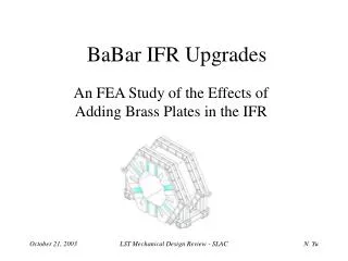
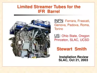
IFR Improvement Phase II(Barrel)Mechanical Engineering Issues H. James Krebs November 15, 2002 H.J. Krebs
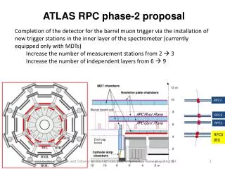
Scope of WorkUnder Investigation • Remove 18 layers of RPCs • Install 7/8” thick brass in slots previously occupied by layers 3,4,6,7,9,10,12,13,15 & 16 – 10 layers (8.75” thickness) • Install detectors (technology TBD) in layers 2,5,8,11,14,16,17 & 18 – 8 layers H.J. Krebs
Modifcation of Detector Loading H.J. Krebs
Present EQ Committee Approval • IFR Improvement Phase I (FWD End Doors) • Add 1” thick layers of brass in door slots 8,10,12,14 & 16 (30 tons) • Add 28 tons of steel absorber on fwd end of doors • Add 3 tons of belt chambers around end door periphery • Remove one counterweight from each door skid (-24 tons) • IFR Improvement Phase II (Barrel) • Add 7/8” thick layers of brass in barrel slots 7,9,11,13 & 15 (60 tons) • EQ Committee approval on 12-18-01 H.J. Krebs
Earthquake Issues for New Scope • Calculate new CGs and determine extent of loading asymmetries • Differential motion between detector and floor slab – cannot exceed 8.5” • Re-do isolator analysis • Strength of floor slab • Strength of X & Z restraint rods and connections to floor and barrel • Connection of Y restraint to floor • Structural analysis of barrel system • Redo “Missing Bolts Analysis” H.J. Krebs
Chamber Removal Issues (General) • At present, the mechanical scope of work does NOT include removal and replacement of layers 1, 19 and the cylindrical RPC • RPC extraction and replacement detector installation shall occur on forward end • Probably committed to whole sextant when starting • Removal of any chamber in a sextant will likely damage other chambers in that sextant due to the bundling of gas lines and HV cables on backward end • Rigid installation work platforms will be needed • Modify end door work platforms? H.J. Krebs
Chamber Removal Issues (General) • Remove fwd end plug for side sextants BL00,BL05,BL03 & BL02 • End doors open – fwd & bwd • Extend travel of fwd doors H.J. Krebs
Chamber Removal Issues (General) • Load transfer of calorimeter weight needed for side sextants • Removal of F-CAL (still under investigation) • Support from upper barrel EQ support beams • Removal of corner plates • Max of 2 plates removed at any time • On forward end only • Continuous position monitoring of detector internals as/after corner plates are removed • Many dial indicators • Layer 18 buried behind flux bars which are buried behind corner plates H.J. Krebs
Layer 18, Layer 19, Corner Blocks H.J. Krebs
Schedule and Installation Issues • Approximately 2 days lost due to photographers, film crews and tours • 3 days lost due to PEP survey at end of run • 3 days lost due to PEP survey at start of run • 3 Days lost due to PPS certification • No access to EMC during chamber removal and installation process • Tooling to install replacement IFR detectors is probably similar in concept but different than RPC removal tooling H.J. Krebs
IFR Sextant BL01 (Top) • Work platforms needed • Remove IFR cabling • Disconnect & remove IFR cooling loops • Remove center gap plate • Solenoid • Disconnect solenoid axial supports • Remove axial support plate • New fixture needed • Release upper radial supports • Remove fwd corner plates at 1:00 & 11:00 • Layer 1 replacement will be difficult • Support plate is cambered H.J. Krebs
IFR Sextant BL00 (Upr East) • Work platforms needed • Remove fwd corner plates at 1:00 & 3:00 • New fixture needed • Remove Gap plates – fwd & bwd • Disconnect and peel back cabling • SVT • Remove IFR cabling • Remove piping • B-CAL N2 vent • B-CAL chilled water return • DCH fwd end plate cooling supply & return (not used) • VESDA line H.J. Krebs
IFR Sextant BL00 (Cont’d) • Solenoid • Disconnect solenoid axial supports • Remove axial support plate • Release upper radial supports • Remove forward end plug • Disconnect fwd east door drive and move door additional 289mm • Remove belt chambers • Transfer calorimeter load – east side • Layer 1 replacement will be difficult • Support plate is cambered H.J. Krebs
Load Transfer H.J. Krebs
IFR Sextant BL05 (Lwr East) • Remove fwd corner plates at 3:00 & 5:00 • New fixture needed • Remove gap plates – fwd & bwd • Disconnect and peel back cabling • F-CAL • B-CAL • Remove IFR cabling • Remove piping • B-CAL N2 vent - F-CAL Source return • B-CAL H2O supply - F-CAL fluorinert supply • F-CAL N2 Supply - F-CAL fluorinert return • F-CAL Source Supply H.J. Krebs
IFR Sextant BL05 (Cont’d) • Solenoid • Disconnect solenoid axial supports • Remove axial support plate • Release upper radial supports • Remove forward end plug • Disconnect fwd east door drive and move door additional 289mm • Remove belt chambers • Transfer calorimeter load – east side H.J. Krebs
IFR Sextant BL04 (Bottom) • Remove fwd corner plates at 5:00 & 7:00 • Remove gap plates – fwd & bwd • Remove center gap plate • New fixture needed? • Remove IFR cabling • Disconnect and remove IFR cooling loops • Solenoid • Disconnect solenoid axial supports • Remove axial support plate • Release upper radial supports H.J. Krebs
IFR Sextant BL04 (Cont’d) • Chamber removal easier if fwd PEP raft support pedestal is removed • Not enough Z clearance for chambers to be nominal 3740mm in length • Interference with PEP concrete pier • Maximum clearance is 3570mm • Good news – layer 18 remains intact at 3340mm • Layers 1 thru 17 limit to 3550mm and position to forward end H.J. Krebs
IFR Sextants BL02 & BL03 • Similar to sextants BL00 & BL05 • Disconnect solenoid hall probe • Not necessary to remove belt chambers on fwd west end door H.J. Krebs
Brass H.J. Krebs
Alternate Materials • Interaction Lengths • Fe ~17cm • Cu ~15cm • Pb ~17.1cm • U ~10.5cm • W ~9.6cm • Pt ~8.9cm H.J. Krebs
Brass Design Option • Layers 3,4,6,7,9,10 equals 62 tons • Would not require EQ Committee approval • Savings of $407K M&S H.J. Krebs
Brass Engineering Issues • Prefer to install brass after reinstallation of all corner plates • Handling fixtures and installation tooling needed H.J. Krebs
Engineering Responsibilities • Jim Krebs (SLAC) • Project Management • Brass design including installation and handling fixtures • Installation platforms • Miscellaneous handling fixtures • Corner plates • Solenoid support arms • Richard Boyce (SLAC) • RPC removal fixtures • Replacement chamber handling and installation fixtures H.J. Krebs
Engineering Responsibilities • Les Dittert (Contract) • Earthquake design and analysis • Knut Skarpaas VII (Contract) • Calorimeter load transfer • Calorimeter support arm handling fixture • Nancy Yu (SLAC) • Finite element analysis H.J. Krebs
EDIA Cost Estimate H.J. Krebs
Fabrication and Shop Labor • Fab & Testing • Shop Labor H.J. Krebs
Installation Labor H.J. Krebs
M&S Costs H.J. Krebs
Total Costs - Mechanical H.J. Krebs
Schedule • Early drafts from ~1.5 yrs ago: • Top sextant only: ~1.5 months • East diagonals: ~3.3 months (no endcap removal might cut this by a month) • These were very preliminary schedules that need update! H.J. Krebs