Download
1 / 23
230 likes | 369 Vues
HHFW heating experiments in NSTX S. Bernabei, J. Hosea, B. LeBlanc, C. K. Phillips, P. Ryan , D. Swain , J. R. Wilson and the whole NSTX crew. ORNL. ORNL. Outline of results. HHFW has several goals for NSTX physics: current drive to extend the pulse plasma heating

E N D
HHFW heating experiments in NSTX S. Bernabei, J. Hosea, B. LeBlanc, C. K. Phillips, P. Ryan , D. Swain , J. R. Wilson and the whole NSTX crew. ORNL ORNL
Outline of results • HHFW has several goals for NSTX physics: • current drive to extend the pulse • plasma heating • plasma startupand other. • Electron heating can be rather efficient depending on the phase of the antenna. • There are some indications of current drive, but in general somewhat disappointing • HHFW achieves H-mode. • But several puzzles remain and need to be addressed theoretically and experimentally. 1
COUPLING Co-CD = 0 - (1/2)pp - (3/2)p = -90° Cntr-CD = 0 +(1/2)pp +(3/2)p= +90° Superdipole = 0 0 pp 0 0 Dipole = 0 p 0 p 0 p = 180° 2
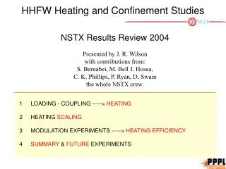
Heating efficiency depends on the plasma edge conditions especially from “inner gap”. Apparently the relevant parameter is plasma shape and position 3
LOADING - COUPLING -----> HEATING • heating efficiency DE/P • inversely proportional to • loading DE/P • loading depends on phase • loading independent of plasma density Loading increases with power: could ponderomotive effects “push” the plasma away and so increasing coupling to surface waves? 4
Edge phenomena show phase dependence and coupling to surface waves • 180° has best heating • (@ t=0.22 there is MHD) • -90° has very high Da • -90° reflected power shows no • time variation • +90° has intermediate behaviour -90° +90°180° THESE FINDINGS POINT TO A DEGREE OF POWER COUPLED TO SURFACE WAVES, ESPECIALLY FOR -90° (CO-CD) HIGH LOADING DOES NOT NECESSARILY MEAN EFFICIENT COUPLING TO CORE PLASMA 5
MODULATION EXPERIMENTS Modulation experiments were performed in order to obtain the percentage of RF power absorbed in the plasma. +30°-90°+90° 180° • Heating efficiency decreases with k|| • 180° has higher power absorption (80%) • +90° (counter CD) is more efficient • than -90° (co-CD) • Power at -30° (theoretically the most • efficient at driving current) has very • small absorption Part of the missing power from the core is radiated to the wall (larger for low k|| ) 6
Derivation ofDEand t at four times (to) total stored energy curve fit E ~ E +DE (1- exp[-(t-to)/t] o o % (pwr. abs.) = DE/(Pt) DE t RF power time to = 0.244 0.310 0.344 0.277 7
% of absorbed power in Helium Different symbol corresponds to different shot As seen before, F=180° heats better that F=-90° This means that a good portion of the power launched at -90° is not penetrating in the plasma core and dissipated in excitation of parametric instabilities and (possibly) in surface waves 8
Tau in Helium -90°180° Stronger heating and lower confinemet time, make absorption of waves at 180° higher than waves at -90° The lower confinement time for 180° is baffling: one possible explanation is that 180° damps at low electron temperature (250-400 eV), therefore off-axis, with consequent low confinement time. (see page 13) 9
% of absorbed power in Deuterium • Deuterium data were not as clean as in Helium • Still 180° and +90° show higher values of absorption than -90° • -30°, which theoretically should give high current drive efficiency, shows <20% absorption 10
Tau in Deuterium The higher percentage of power absorbed at +90° appears to by due to the lower confinemet time. This is a puzzle which needs to be understood. 11
Low frequency MHD during heating • Two modes: both with n=1 (and m=1 or m=2) both responsible for heating saturation and losses • (the possible explanation for its destabilization is discussed in the next section) 12
Indications of current profile broadening at 180° good heating at 180° decreasing of li = broadening increase of qo red RF power (black: shot at -90° at lower power, used as reference in absence of a no-RF shot) MHD Is this direct current drive generated by RF power or Bootstrap? 13
q-profile modified during RF with F = 180° Reconstruction of the q-profiles before RF at t=0.15 sec and after 60 ms (t=0.21) shows a broadening around q=2 (see poster) This is consistent with: off-axis heating (see TS) decrease of li increase of qo destabilization of MHD modes power = 2.0 MW phase = 180° 14
broad Thomson scattering profiles for F=180° MHD ne Teo RF power Ip profiles at t=0.21 before MHD profiles at t=0.15 before RF 15
MHD for the same three shots shown at page 5 The three shots have same net power. A strong mode is seen at 180°; weaker at +90° and absent at -90° Even if the power absorption for -90° is smaller than for 180°, the threshold for MHD destabilization is smaller for 180° ( 1 MW) than for -90°. +90° is intermediate. 16
Like in the early LH experiments, in which it was assumed that LH was responsible for MHD instabilities, during application of HHFW power it is NOT the RF power that excites MHD, but it is rather the current profile change due to RF power that excites MHD. • Therefore every observation is consistent with a broadening of the current profile during HHFW at F=180° (direct RF or bootstrap ?) which causes a steepening of the profile around q=2. • Note from the Coupling figure that, because of the strong tilt of the field lines, 180° does not produce a symmetric spectrum. In addition there is a strong residual electric field which augments the asymmetry. • -90° has much smaller effect, while +90° an intermediate one: • This could be due to the lower absorption efficiency. gkgh But it might also indicate that higher k|| are required for current drive. 17
HEATING SCALINGS Example of power fit for texp vs. total power All the shots are included in the two plots on the left, vs. H-mode scaling and Lthermal scaling. The points fall samewhat in between. 18
Confinement trends point toward moderate Ip and maximum BT Each point represents a shot: spread is due to power. Only shots with power between 1 MW and 2 MW are plotted. 19
Summary • HHFW heats electrons: heating efficiency ranges from ~80% to ~20% and is strongly proportional to k||. (see CO3.0.12 J. R. Wilson) • An important parameter for this disparity in power absorption with different k|| appears to be due to the plasma conditions in front of the antenna (density, shape and possibly geometry). • Low k|| seem to dissipate part of the power in parametric instabilities and surface waves. (see JP1.014 S. Diem) • Looking at the power dissipated in parametric waves and to the radiated power we are not yet able to account for all the power that is launched in the vessel • Difference between -90° and +90° is a puzzle. • MHD modes, either (1,1) or (2,1), cause degradation of the heating efficiency. They appear to be caused by current profile change. • Heating scaling falls somewhat in between H-mode and Lthermal scaling (see also JP1.009 LeBlanc, JP1.012 Hosea, JP1.0013 Phillips, CO3.013 P. Ryan) 20
Proposed experiments • Reverse the magnetic field to determine if the difference between -90° and +90° is due to geometrical constraint. • Use edge probes, surface reflectometer, Rogowski coils between plates and wall to determine if (and how much) RF power is coupled to surface waves and dissipated in sheaths. • Change edge conditions and configuration to understand coupling. • Complete modulation experiments, varying phase (power? Ip? B? ne?) and gas (Deuterium data were not very good). • Use X-ray diagnostics perpendicular and parallel to look for asymmetry in the electron distribution in the z-direction (CD?) 21
The first author, sbernabei@pppl.edu , would welcome very much constructive comments; please direct any criticism to the presenter.