Download
1 / 34
360 likes | 644 Vues
Physics of Bridges. Bridge Building Project. Unit Objectives. Define tension and compression and explain how materials react to these forces Define the three types of stresses a material experiences when forces are applied

E N D
Physics of Bridges Bridge Building Project
Unit Objectives • Define tension and compression and explain how materials react to these forces • Define the three types of stresses a material experiences when forces are applied • Understand how scientists test materials to obtain a stress-strain curve • To identify types of bridges
Unit objectives continued • Grasp the concepts of equilibrium, static and dynamic loads, vibrations, and resonance • Construct a bridge to hold a subjected static load.
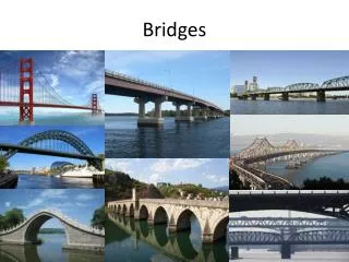
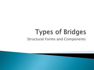
Lesson 1: Types of Bridges Arch Bridges Suspension Bridge Beam &Truss Bridges
Beam Bridges 1. Simplest and least expensive to build Elk Avenue Bridge: Tennessee
2. Beam bridges will feel both compressional and tensile forces, thus they tend to sag between the piers; this problem can be countered by adding steel girders underneath the beam.
When a load pushes down on the beam, the top portion of the beam is pushed together by a compressive force while a tensile force stretches the lower portion. The farther apart the supports or piers, the weaker a beam bridge becomes.
Truss Bridges Trusses are used to stiffen and support a bridge by distributing the loads and forces acting upon the bridge based on the positions of the vertical, horizontal and diagonal chords. They are based on triangular configurations. How those chords are arranged identifies the type of truss. Betsy Ross Bridge: Philadelphia
Warren Truss Pratt Truss Matsuo bridge in Japan is a 4 span truss bridge.
Forces on Truss Bridges 1. Forces are carried along the axis of the assembled members that form the triangular shape. 2. The forces on the truss members are tensile or compressional but not both. 3. The members which hold the deck may experience both tension and compression forces, which make analysis very complex.
Arch Bridges Key Points: 1. The arch takes (transmits) the load from the deck of the bridge to the land on both sides Arlington Bridge in Washington DC
2. Downward force from the top of an arch is carried along the curving form all the way to the base (abutments). At the same time, the ground pushes up with equal force. As a result, each of the arch's sections are tightly squeezed, or compressed, by adjacent sections, making the structure very rigid
3. Materials that handle compression well are typically used in construction of arch bridges; like stone, concrete, and metal Roman Arch Bridge constructed of stone Iron Arch Bridge in England
Suspension Bridges Suspension bridges are easily recognized by the large towers and the cables that hold up the road deck. Some examples are the Brooklyn Bridge in NYC and the Golden Gate Bridge in San Francisco. The cables are attached on top of the pylon and then pulled down in a parabolic shape down to two anchor points on land. One major disadvantage to suspension bridges is its reaction to wind. The roadway is held up by the cables, while the cables are held in place by the towers.
A suspension bridge is one where the road deck is suspended from cables that are strung across the river (or whatever the obstacle happens to be). There is no support in the center of the span and the deck hangs below the supports rather than resting upon them. Verrazano-Narrows Bridge: NYC
Forces on Suspension Bridges Red Arrows show tension Blue Arrows show compression
Lesson 2 Concepts of compression, tension and loads Force: a push or pull in any direction ex: weight of bridge, wind, any load on bridge Every force on the bridge causes the bridge to react even though it may not be noticeable (Newton’s 3rd Law) When forces are applied to a structure and added together, the sum of the forces is defined as a load. 2 types of loads engineers consider: dead load (static load): weight of bridge and stationary objects on the bridge live load (dynamic load): objects in motion as well as natural forces (wind, earthquake)
As stated before, for all forces acting on a bridge, there must be a counter force pushing or pulling in the opposite direction These forces are defined as either compression or tension forces. Tensile force: lengthens or pulls on a material Compression force: squeezes or pushes on a material ExampleTake a two-by-four and place it on top of two empty milk crates -- you've just created a crude beam bridge. Now place a 50-pound weight in the middle of it. Notice how the two-by-four bends. The top side is under compression and the bottom side is under tension. If you keep adding weight, eventually the two-by-four will break. Actually, the top side will buckle and the bottom side will snap.
Not all structures experience solely tension or compression. 2 equal and opposite forces acting parallel or at an angle to the axis of a structure are called axial forces. When 2 forces are not directly opposite each other, shearing may occur, and this is called a non-axial force.
Truss Bridge Builder • http://www.jhu.edu/~virtlab/bridge/bridge.htm
Lesson 3 A bridge member under tension, compression or both forces at the same time experiences what engineers define as stress. “Stress is how hard the atoms and molecules which make up the material are being pushed together or pulled apart as a result of external forces” - JE Gordon Two pieces of the same material that undergo a stress testing will yield the same stress limit irrelevant of shape of the material To calculate stress: Stress=force/cross-sectional area Breaking force on A=60 N while breaking force on B=120N Breaking stress in more useful than breaking force because it takes into account size of the material
The elongation or shortening of a material under stress is called strain. Strain is a measure of how far a material is being pulled apart or pushed together, and like stress, is dependent only on the type of material. To calculate strain: strain=ΔL / L change in length / original length Steel in a stress test exhibiting strain.
Who cares? What’s the point? • For stress or strain to be of any practical value to engineers, a graph of stress (y-axis) vs. strain (x-axis) is plotted. • The slope of this curve is usually a straight line: thus it obeys Hooke’s Law of deformation. • The slope will vary for different materials • Engineers use this curve to measure how readily a material temporarily deforms and returns back to original shape after a load is removed. • It is important that a material acts like a spring (returning to original shape) because permanent deformation will cause an object to break more easily. • This curve is called Young’s Modulus of Elasticity measures the stiffness of a material and at what point the maximum elastic deformation will occur. • Depending on the application, engineers may desire a material with a low Young’s modulus of elasticity like rubber, or a high one like steel.
The amount of stress a member can tolerate is crucial when selecting materials for a bridge. Engineers analyze every component of a bridge to determine what members will result in compression, tension, or both. Certain materials are better under compression rather than tension like: concrete, brick, hard woods. There are materials like pre-stressed concrete that can carry both tensile and compressional forces because it has steel rods running through it. After engineers have determined the forces acting on members of a bridge, they refer to reference books for the stress-strain limits of specific materials.
Modulus of Elasticity: Sample Problem • Young's modulus, E, can be calculated by dividing the tensile stress by the tensile strain: • where • E is the Young's modulus (modulus of elasticity) measured in pascals; • F is the force applied to the object (Newtons); • A is the original cross-sectional area through which the force is applied (m2); • ΔL is the amount by which the length of the object changes (m); • L is the original length of the object (m).
Sample Problem • Determine the deformation in a column of titanium that has a length of 1.0 m and is 2 cm x 2 cm in cross-section; when a load of 10 kN is placed on top of it. • (Ε= 1.2 x 10¹¹ Pa for titanium)
Solution • Given: L=1 m A= .02 x .02= 4 x 10⁻⁴m Ε= 1.2 x 10¹¹ Pa F= 10 kN= 1x 10⁴ N Find ΔL - Ε=FL/A ΔL rearrange to get ΔL by itself • ΔL = FL/EA • Substitute values in and solve • ΔL = 2.1 x 10⁻⁴ m
Sample Problem • A steel wire of length 2.06 m with circular cross section must stretch no more than 0.290 cm when a tensile force of 350 N is applied to each end of the wire. What minimum diameter is required for the wire? (Young’s Modulus of steel = 2 x 10¹¹ Pa)
Solution • Given: L=2.06 m ΔL=.29 cm= 2.9 x 10⁻³ m Ε= 2 x 10¹¹ Pa F= 350 N need to find diameter, which is part of the cross-sectional area of a circle (Πr2) r=d/2 so… Πr2= Π(d/2)2= Πd2/4=A Now we can solve for diameter using Young’s modulus formula • Ε=FL/A ΔL rearrange so A is by itself • A=FL/E ΔL substitute in for A • Πd2/4= FL/E ΔL • Πd2/4= (350 x 2.06)/(2 x 1011 x 2.9 x 10-3 ) • d= .00127m or 1.27 mm