System Five Control Box Performance Menu Settings
Customize System Five for performance enhancement with menu settings. Adjust gains, elevation, slope control, valve offsets, and averaging for optimal results. Access settings easily with step-by-step instructions.


System Five Control Box Performance Menu Settings
E N D
Presentation Transcript
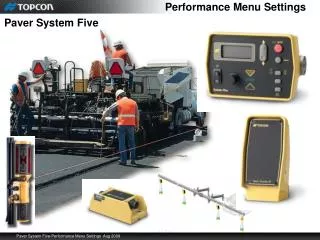
Performance Menu Settings Paver System Five
Performance Menu Settings • Performance Menu Settings: The System Five Control Box Performance Menu settings are a series of features that allow System Five to be modified for operator or performance enhancement. The factory settings are presets values that will run most pavers, however machines that are equipped with proportional valves (Caterpillar) adjusting valve offsets will be required.
Performance Menu Settings • Accessing Performance Menu: Turn power off. While holding down the Set/Menu button turn the box back on. The Auto LED and Grade Adjustment Direction arrows will flash.
Performance Menu Settings • Accessing Performance Menu: Rotate the Grade Adjustment Knob to scroll through the menu selections on the LCD.
Performance Menu Settings • Accessing Performance Menu: Press the Auto button to select a menu item.
Performance Menu Settings • Accessing Performance Menu: Turn the Grade Adjustment Knob to view the options available from the Menu selection.
Performance Menu Settings • Accessing Performance Menu: Press the Auto button again to store vale. To access other Menu settings, turn the Grader Adjustment Knob. To exit the Performance Menu, press the Set/Menu button.
Gains Gains: • Gains determine the speed at which System Five allows the tow point cylinders to adjust to a change in either the elevation or slope control. For faster hydraulic response, increase the gain value. • The objective is to set the gain so the screed reacts to the change in grade quickly, but without “overshooting”. • Tracker placement can achieve grade changes quicker than adjusting Gains • Before setting the Gain, make sure the machines hydraulic flow control valves are adjusted for proper cylinder speed according to the manufacture’s recommendations. Typical cylinder speed is 15-20 seconds for full up or down cylinder travel. (Solenoid valves only)
Elevation Gains Gains (Elevation): • From the Performance Menu, select elevation gain and press the Auto button . • Turn the Grade Adjustment Knob to select the desired value, typically 25 for most paving applications. • Press the Auto button again to store the value. • Press the Set/Menu button to exit. • Gain Elevation Value Range: 1-200 • Factory Preset: 25
Slope Gains Gains (Slope Control): • From the Performance Menu, select slope gain and press the Auto button . • Turn the Grade Adjustment Knob to select the desired value, typically 25 for most paving applications. • Press the Auto button again to store the value. • Press the Set/Menu button to exit. • Gain Elevation Value Range: 1-200 • Factory Preset: 25
Valve Offsets Valve Offset • The valve offset is the minimum amount of electrical signals sent to the valve which causes the hydraulic cylinder to move. If the valve offset is too small, the sensor will not reach on-grade. Likewise, if the valve offset value is too large, the sensor will move too much and overshoot On-Grade. • Solenoid Valves work on factory preset 135 • Proportional Valves require setting offsets (Caterpillar Pavers)
Valve Offset Raise Valve Offset: From the Performance Menu, select Valve Offset (OFS) and press the Auto button. This will automatically activate the valve screen for Raise Offsets. The raise grade correction display arrow illuminates, and the Control Box will begin sending a raise correction signal to the valve. Turn the Grade Adjustment Knob counter clockwise, decreasing the valve offset until the hydraulic cylinder no longer moves. Then slowly rotate the Grade Adjustment Knob clockwise until the hydraulic cylinder just begins to move up. Press the Auto button to store the Raise Offset Value and switch to the Lower Offset.
Valve Offset Lower Valve Offset: • Turn the Grade Adjustment Knob counter clockwise, decreasing the valve offset until the hydraulic cylinder no longer moves. Then slowly rotate the Grade Adjustment Knob clockwise until the hydraulic cylinder just begins to move down. • Press the Auto button to return to the Performance Menu. • Press the Set/Menu button to exit the Performance Menu. • Caterpillar Pavers mark left and right boxes. • OEM Caterpillar installs • May be set to Solenoid • May have performance and Tech setting not at factory defaults. • May have custom cables with out config res.
Averaging Averaging: • This setting changes the amount of dampening, or filtering, applied to sonic tracker and laser receiver measurements. It can be thought of as the time period over which a running average of the elevation measurements, allowing the system to react more quickly to smaller grade changes. • A large value will average more elevation measurements, preventing the system from reacting to undesirable items close to the reference. This will also make it less susceptible to fluctuations in temperature or small obstructions. • Averaging value range 1 to 100 • Factory preset 50
Averaging Averaging: From the Performance Menu, select Averaging then press the Auto button. Turn the Grade Adjustment Knob to select the desired value. Press the Auto button to store the value. Press the Set/Menu button to exit the Performance Menu.
Elevation Deadband Elevation Deadband: • Deadband is the area of the Working Window that is on-grade. While the reference is within that area, the paver’s valves are closed. Therefore the wider the Deadband (on-grade area), the more a reference can move up or down without a correction being initiated. Once the signal from the reference is out of the deadband, the control system will drive the hydraulics to place the reference back in the CENTER of the deadband. • Deadband Elevation value range 1 to 30mm • Factory preset 3mm (01’ or 1/8”)
Elevation Deadband Elevation Deadband: From the Performance Menu, select Elevation Deadband and press the Auto button. Turn the Grade Adjustment Knob to select the desired value typically 3mm. Press the Auto button to store the value. Press the Set/Menu button to exit the Performance Menu.
Slope Deadband Slope Deadband: • Deadband is the area of the Working Window that is on-grade. While the reference is within that area, the paver’s valves are closed. Therefore the wider the Deadband (on-grade area), the more a reference can move up or down without a correction being initiated. Once the signal from the reference is out of the deadband, the control system will drive the hydraulics to place the reference back in the CENTER of the deadband. • The wider the Slope Deadband, the greater the slope can vary without initiating a correction. • For example, if the operator is grading at a 2.0% slope and the deadband is set at .10%, the system reads on-grade anywhere from 1.95% slope to 2.05% slope. • Deadband Slope value range .025% to .75% • Factory preset .075%
Slope Deadband Slope Deadband: From the Performance Menu, select Slope Deadband press the Auto button. Turn the Grade Adjustment Knob to select the desired value typically 075. Press the Auto button to store the value. Press the Set/Menu button to exit the Performance Menu.
Beeper Beeper Alarm: When in Automatic Mode and the Sonic Tracker receives a reference signal outside of the Working Window (more than 2.0” from grade), a single audible beep will be heard. From the Performance Menu, select Beeper press the Auto button. Turn the Grade Adjustment Knob to turn the beeper ON or OFF. Press the Auto button to store the value. Press the Set/Menu button to exit the Performance Menu.
Units Units: • The Unit item sets the display to read in feet, inches, or centimeters. • From the Performance Menu, select Units press the Auto button. • Turn the Grade Adjustment Knob to select a unit for measuring. • Press the Auto button to store the value. • Press the Set/Menu button to exit the Performance Menu. • Inches each click=1/20” less than 1/16” 5 clicks to a 1/4” • 1.00 • 1.05 • 1.10 • 1.15 • 1.20 • 1.25
Test Test: This menu item tests the valves for shorts and disconnected valves. From the Performance Menu, select Test Mode (tSt) press the Auto button. Press the Auto button to test the Raise valve. Press the Auto button to test the Lower valve. Press the Set/Menu button to exit the Performance Menu.
Performance Menu Settings Paver System Five