Download
1 / 17
190 likes | 377 Vues
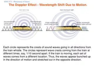
Blood Flow Measurement Due to Doppler Effect. EE01083064 EE01083293. Introduction. Beam of ultrasound with a transmitted frequency f T is transmitted and reflected back from the red blood cells. f D = f T (2v/c) cos θ f T = Transmitted frequency f d =Doppler shift frequency

E N D
Blood Flow Measurement Due to Doppler Effect EE01083064 EE01083293
Beam of ultrasound with a transmitted frequency fTis transmitted and reflected back from the red blood cells. fD= fT(2v/c) cosθ fT= Transmitted frequency fd=Doppler shift frequency θ = angle of incidence C= the velcity of ultrasound
According to the Equation fD= fT(2v/c) cosθ The signal reflected back contain the information about the velocity of the blood and direction of blood flow. How Can we Extract these Information from the Signal??????
Mixing • Process to find these terms. • This is done by simple possible system contain oscillator. • This drives the trasmitting crystal at its resonant frequency. • Resonant frequency would be 10MHZ for superficial blood vessel and 5MHZ or less for deeper vessels such as aorta or the aliace arteries.
The Received crystal converts the reflected ultrasound energy into an electrical signal . • Then it is amplified by RF amplifier. • Then multiplied by transmitted signal. • Further there is a low pass filter to take just Doppler frequency.
Mathematical Calculation AT = A cosωT t AR = B cos(ωT+ωD) t AT Transmitted Signal AR Received Signal V= AT xAR V= A cosωT t x B cos(ωT+ ωD) t V=AB/2 cos(2ωT+ ωD)+AB/2 cos(ωD t)
Limitations of this Simple System • The Direction of Blood Flow is Lost. • Due to these limitations, It is only used for simple test such as detection of deep vein thrombosis.
Solution for this Limitation(Zero crossing Detector) • Have two separate demodulator channels, one for forward and other for reverse flow. • Use zero crossing detectors to decide the direction of blood flow.
Received signal is multiplied by Ecosωt and by a phase shifted version of transmitted signal E cos(ωt+φ) • If received signal is same as AR=Bcos(ωt+ωD) then VB= BE/2cos(ωDt) ……….(1) so, VA =BE/2cos(ωDt-φ) ……….(2) So, signal is two channels A & B are identical apart from a phase shift φ ∠ VB - ∠ VA = φ
True Directional Doppler Demodulation System • Preserves all the directional information in the signal • Combination of previous circuit and some new components. • Has limitation that It does not do frequency analysis of the reflected signal.