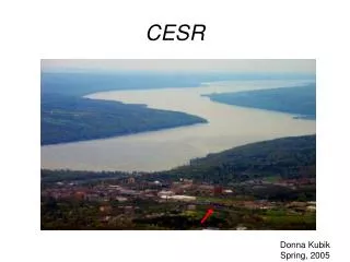
CESR as Light Source
This document provides a comprehensive introduction to the Cornell Electron Storage Ring (CESR) and its operational status, focusing on multi-bunch optics, low emittance tuning, and various beam configurations. It discusses the capabilities of CESR to operate with counterrotating beams of electrons and positrons, the energy ranges, and the performance improvements over time, including low emittance layouts and ongoing research and development efforts to optimize beam characteristics and stability. Also covered are the advancements made in each operational phase at the CHESS site.

CESR as Light Source
E N D
Presentation Transcript
CESR as Light Source David L. Rubin for the CESR Operations Group Cornell University Laboratory for Elementary-Particle Physics
- Introduction to CESR - CESR Operating Status - Multi-bunch optics - Low emittance tuning - Single beam optics - Low emittance layout CHESS Site Visit
CESR • CESR operates with counterrotating • beams of electrons and positrons • - Beam energy ranges from 1.5-5.5 GeV • Injector • - Linac ~ 300MeV electrons & 150MeV • positrons • - Synchrotron booster accelerates to full • storage ring energy • - Linac/synchrotron cycle at 60Hz • - Electron gun pulses at up to 72MHz • to fill CESR with bunches spaced 14ns • Bunch configuration • - Traditionally 9 equally spaced trains • - As many as 6 bunches/train with • 14ns spacing • - Itotal ~ 250 mA/beam CHESS Site Visit
CESR operating status CHESS optics Electrons 200 mA - 30 bunches Positrons 180 mA - 22 bunches Lifetime ~ 12 hours Fill length ~ 3hours h ~ 140 nm v ~ 1-2 nm X-ray beam position stability < 30 m. CHESS Site Visit
CESR operations Sunday operation Ion trapping 23.25 hours beam 23.5 hours beam CHESS Site Visit
CESR multi-bunch operation Colliding beam configuration 4 electrostatic deflectors generate differential closed orbit distortion that separates electron and positron bunch trains. 9X5 Beginning fall 2008 interaction region low optics replaced with simple FODO lattice structure. (L0) Vertical separators removed (L3) and the 9X5 configuration is no longer viable. CHESS Site Visit
CESR multi-bunch operation Beginning September 2009 10 trains 4 bunches/train electrons and positrons CHESS operation today 4 positron trains and 6 electron trains with 6 bunches/train CHESS Site Visit
Low Emittance Tuning Having removed the low- insertion and CLEO 1.5T solenoid and rotated IR quadrupoles and vertical separators We have eliminated sources of transverse coupling, vertical dispersion and vertical beam size New optics configuration permits significant reduction in vertical emittance Operation with counterrotating beams limits the number of bunches. High bunch current /good lifetime/ low vertical emittance are mutually exclusive CHESS Site Visit
Low Emittance Tuning • -Principle component of the CesrTA project is to reduce vertical emittance • and develop procedures to monitor and maintain low emittance • -Survey and alignment - survey network • -Digital beam position monitor electrons will permit single bunch/single pass • real time nondestructive measurement of • - Orbit • - Optical functions • - Transverse coupling • - Dispersion • On line analysis and modeling software will deploy corrector magnets • (vertical steering, quadrupoles, skew quads) to • preserve minimum emittance as well as beam position CHESS Site Visit
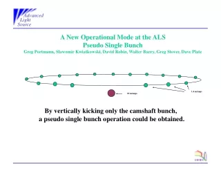
Accelerator R&D Single beam operation? “Pretzel” configuration (electrons and positrons) - Constrains optics (precludes low horizontal emittance) - Complicates injection (injected bunch collides with opposite species stored beam) - Limits number of bunches - Impedes low emittance tuning (beam is off axis in all magnets) Single beam(positrons) - Lower horizontal emittance optics - More bunches (lower bunch current, smaller vertical beam size, longer lifetime) - More efficient injection (top off ?) - Reduced vertical emittance - No ion trapping CHESS Site Visit
Single beam optics Based on existing Ring layout (Machine studies experiments are underway) 5GeV Positrons >180 bunches I = 250mA h = 50nm v ~ 200pm CHESS Site Visit
Low Emittance layout Rearrange hard bends for single beam operation - Lower horizontal emittance - Space for undulator/wiggler Existing layout Low emittance (single beam) layout CHESS Site Visit
Lattice development CHESS Site Visit
Summary • Today - 2 beam operation ~ 175mA/beam, 52 bunches • Beginning Fall 2009 - 2 beams, 225mA/beam (80 bunches) • Single beam existing layout (?) Positrons, 250mA, >180 bunches, 50nm • Single beam - low emittance layout Positrons, 250mA, >180 bunches, 15nm CHESS Site Visit