Download
1 / 16
160 likes | 295 Vues
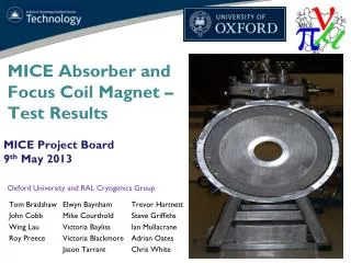
MICE Absorber and Focus Coil Magnet – Test Results. MICE Project Board 9 th May 2013. Tom Bradshaw John Cobb Wing Lau Roy Preece. Oxford University and RAL Cryogenics Group. Elwyn Baynham Mike Courthold Victoria Bayliss Victoria Blackmore Jason Tarrant. Trevor Hartnett

E N D
MICE Absorber and Focus Coil Magnet – Test Results MICE Project Board 9th May 2013 Tom Bradshaw John Cobb Wing Lau Roy Preece Oxford University and RAL Cryogenics Group Elwyn Baynham Mike Courthold Victoria Bayliss Victoria Blackmore Jason Tarrant Trevor Hartnett Steve Griffiths Ian Mullacrane Adrian Oates Chris White
Commissioning Programme • Since the magnet was delivered and installed in R9 hall we have performed the following: • System set-up and operation check • Leak check magnet under vacuum and pressure • Pre-cooling with LN2 to 80-90K • Cool-down with Helium to 4K • Steady state thermal performance check zero boil off • Cryocooler excess performance check • Step by step current ramp to full current (Solenoid mode) • Thermal performance check • Step by step current ramp to full current (Flip mode) • Thermal performance check Pre-cooling with liquid nitrogen and cooling down to 4K: This talk will go through the results of the powering tests, conclusions and the way ahead.
Instrumentation and control Operating points for the magnet in the various modes are as follows:
Run Summary Quench history is such that the training is taking longer than expected (or we would like) Remember that this acceptance is the responsibility of Tesla although the process necessarily involves RAL personnel Runs and results A “run” occupies approximately two people from RAL for 2-3 days although we have previously had 3-4 people from DL in attendance to capture events.
Quench behaviour Bore of the cold mass Bottom of He Chamber Left at 30A overnight then started from that position the next day Stable temperatures right up to the event
Voltage taps • Showing the location of the voltage taps and how they are wired into the QD system • Thresholds are set at 600mV across the coils Ch3&4 and 20mV for the HTS and LTS leads
Cryocooler Cooling Power The cryocooler cooling power is decreasing and/or the heat load is increasing: .. Green – He chamber Purple – He bath pressure Red – Bath heater status 26% • The red line is the bath heater that is activated when the pressure falls too low • In recent times the heater has not been active • A lot of this time the gas pack was attached and the cooler was condensing – this is not recorded • Certainly the period leading up to the quench on the 24th April all valves were shut • Bath pressure rises until the cryocooler cooling power matches the heat load
Cryocooler Cooling Power Checked that the pressures in the closed cycle refrigerators has not dropped: No issue with this – remains a puzzle
Temperatures post quench Not a huge indicator of where the problem lies but .. Temperatures at top of coil#1 hotter than #2 Temperature sensors 11&15 (top) off coil #1 and 12&16 (bottom) off coil#2 – HTS leads near the coils
Quench data 7th March quench data Slight “bump” before quench Quench Difficult to interpret the traces – after the “event” all sorts of things happen – we did get some sparking in the dump resistors which has now been fixed. Trace indicates that coil#1 is more resistive than coil 2
Quench data Quench is not too dramatic … • Recovery from a run is difficult – best to leave on cryocoolers for a few days to bring temperature down then top up with Helium • Otherwise – use a lot of helium.. • Run cycle is probably 4-5 days Victoria Blackmore was quick enough to catch this….
AFC#2 OVC and Helium Turret • AFC#2 is being completed and will be tested in R9 on delivery from Tesla. • The experience from the testing of module #1 will be invaluable. • AFC#2 should be finished June Radiation Shield
Summary • Looks as though training on module #1 will continue but may take ~ 6 runs (~4 weeks?) • If magnet is not training then we may want to take decision to switch horses and start work on module #2 • Commissioning of module #2 may be delayed because of module #1
Summary and Conclusions Summary of where we are and what has been achieved: • Note that there is little to say on Controls and monitoring – we had a few minor glitches but the DL group did very well….. • Had issues with networking • Level indicator not on board yet … There are some things that we don’t yet fully understand or need to do: Cryocooler cooling power and related pressure; Cryocooler sock insulation to reduce load (?); suspension system tension; Training behaviour
Schedule • The schedule is regularly reviewed but we don’t have a clear view because of the training required. Have to decide, based on training how to proceed when module #2 is available – do we jump horses ? • CERN mapper won’t be back until August .. – would it be better to keep #1 cold ? Make our own checks …? • Need to confirm planning with CERN over this.