Access Networks
180 likes | 208 Vues
Learn about users networks, hybrid networks, xDSL, optical communications, radio networks, and more in this detailed lecture from 2008/09. Understand the different types of access networks and their components.

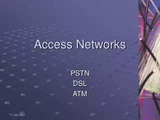
Access Networks
E N D
Presentation Transcript
Access Networks Lectures Lecture 3 - 2008/09 – w.t. Part 3. : Classification of Access Networks
AN: • users networks • hybrid n. (xDSL) • optical… • radio communications network • TV cable distribution system (network) • power lines communications network
3.1 Users networks (PSTN) Exchange MDF ED user distrib.frame network distr.frame track distr.frame Main distribution frame = MDF) user c. (station line) track cable connecting cable network cable Obr.3.1 Example of flexible users network[1]
3.2 Hybrid networks • partially Cu and partially optical cables = optical feeder + transmission system for Cu-wires pair Local exchange (the services node) Customer Cu-pairs ODN ADSL ONU NT OLT VDSL NT ONU OLT UNI SNI Obr. 3.2 Hybrid network architecture
- several different xDSL systems – the new systems in original Cu net with different distances (reach, range) End Cable distribution box Cable distribution box Distribution cable Main cable Main Network LE Fig.3.3
(DSL = Digital Subscriber Line) xDSL: IDSL = ISDN DSL (ISDN-BRA dig. user connection) HDSL – High bit rate DSL SDSL – Symmetric DSL (Single line DSL) VDSL - Very high bit-rate DSL ADSL – Asymmetric DSL • then: - ADSL 2 • - ADSL 2+ • - RE-ADSL 2 • - RADSL
ADSL Teleph. network LP LP High speed channel Control channel V -interface T - interfaces Network side Connecting line User side LP – low pass filter HP – high pass filter Fig. 3.4 Telephone access + ADSL system
connecting line Telephone netw. /ISDN Splitter Splitter T- interfaces e.g. ATM network Connecting line: basic trunk, e.g. with 10 pairs of Cu wires S- interface Network interface PA – Access point User station Fig. 3.5 ADSL system in Cu-connecting lines principle
ADSL specifications: • - modemson each end of twisted pair....3 informationchannels, including basic teleph.service (POTS= Plain Old Telephone Service), filters • modemsare consistentwith basic frames T1, E1 (see Switching technology) • downstream speed – depends on: Cu-line length, wire diameters, bridged taps, crosstalks • Attenuation of lineincreaseswith both its lengthand frequency, decreases with increasing wire diameter (or cross-section) Tab.3.1 Requested phys. parameters of ADSL lines
VDSL (see also fig.3.2 and 3.3) Cu-connecting line Cable branching Telephone netw. /ISDN Splitter Splitter T- interfaces optical connecting line e.g. ATM net 300m-500m! S- interface Network interfaces User station Fig. 3.6VDSL system in hybrid network - architecture - statistical multiplex: . . .
ISDN – line – for rarely connecting to the Internet Fig. llustration of ISDN lines [2]
V5.x Transit network Local Exchange AN Users Interfaces V5.x foruser systems connecting • interfaces between AN and exchange • are defined by ETSI and ITU (G.964/965) • they do not depend on outputs of differents AN types including radiowave AN • possibility of interconnecting networks of different operators Fig. 3.7Architecture of the network with interfaces V5.x - differences between V5.1 a V5.2: ... - see next tab.and figure
Exchange Access device of AN channels channels Network of ren circuits Access device of AN Fig. 3.8Example of architecture of AN with both interfaces V5.x
they support also analogue user lines - interfaces protocols - seefig.3.9 and 3.10 switching system Analogue user terminals control of access network control of access network Physical layer of access network Physical layer of access network Obr. 3.9 V5.2 interface communications protocol
Switching syst. KBPS-TE Access netw. Communications process from end point of AN – request for dispose communications channel... - data transmission (by onother protocol) -request for disconnect Fig.3.10An example of process of creating and aborting connecting, which was initiated from dig. user line.(by protocol BCC-part od protocol V5.2
Referencie: [1] V.Kapoun: Přístupové a transportní síte. VUT v Brně, 1999. [2] Vaculík: Prístupové siete. ŽU v Žiline, 2000. [3] J. Vodrážka: Přenosové systémy v přístupové síti. ČVUT, 2003. [4] Wikipedia, http://en.wikipedia.org/wiki/Image:Tdma-frame-structure.png#file [5] G.Fairhurst: MAC. http://www.erg.abdn.ac.uk/users/gorry/course/lan-pages/mac.html [6] K.Blunár, Z.Diviš: Telekomunikačné siete, časť IV..- skriptum ŽU v Žiline, 2000.