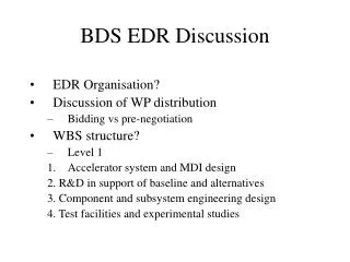
BDS layout
This document outlines the global design effort considerations for minimizing costs and optimizing layout configurations in the beam delivery system. From tunnel diameter adjustments to shaft placements, various aspects are explored to enhance efficiency and reduce expenses.

BDS layout
E N D
Presentation Transcript
BDS layout Extract from today’s talk given to DCB August 22 Full version at http://www-project.slac.stanford.edu/ilc/acceldev/beamdelivery/rdr/docs/BDS_for_DCB_August_22.ppt Global Design Effort
Tentative layout of 14/14 configuration • Common IR hall 100L*30Wm at z=0 with 28.4m separation of IPs • 15m shafts equipped with elevator and stares in IR hall • 4m tunnels in all BDS • Straight tunnel which goes to IR1 (for multi TeV) • Tunnel going to IR2 follows the beamline • Alcoves 4*6m every 100m, no service tunnel • Halls for dump cooling system 35*20m • Small 0.8m shaft for lasers near laser wire, upstream and downstream diagnostics • Passages near muon walls (main and spare one) • 9m machine access shaft near BSY • Shortened extraction line • Shorter tapered tunnels. Etc. Global Design Effort
CF&S cost minimization considerations in new layout • Removing service tunnel and use alcoves • Reducing tunnel diameter from 5m to 4m • (use the fact that swing of BDS in 20/14mr is smaller than in 2mr) • Reduce BSY tunnel separation to 3m • Assume that CF&S will change methodology of tapered tunnel costing • Remove detector service cavern • Minimize number of shafts in IR • Cost min collider hall, assign the difference to detector (to be discussed with Detector colleagues) • Removing cost of e+ bypass line from BDS Global Design Effort
Tunnel with alcoves • If alcoves of 4*6*4m3 are placed every 100m, the cost of the single tunnel seem to increase by 10-20% • The interval of 100m is determined by BPM electronics, and cable cost. Finding the optimum dL and alcove size requires more study • To evaluate the cost difference, one need to add • cost of any additional shafts (assess and “laser shafts”), their caverns, surface buildings • cost of alcoves in all tunnels (including e+ if it is present) • cost of vibration mitigations for pumps • any additional air cooling which may be required • etc. • Without the service tunnel, the reliability and tune-ability of the system are affected, but it is hard to estimate the corresponding cost impact Global Design Effort
T stability • For beamline stability, set a goal of <100W/m deposition into the tunnel (like in best light sources) • Would like to have • Air: 0.2degC over 1hour, 2degC over 24hours • LCW: 0.1degC over 1hour, 1degC over 24hours • But do not yet know what the cost of these reqts • With alcoves, this is more of an issue • The absolute T also matters • if T is too high at work, and need to drop T during access, this is major stability concern • Under discussion now Global Design Effort
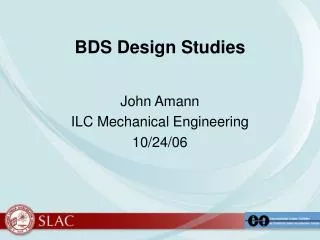
Tunnel diameter in 14/14 • In 2/20 config, was using 5m tunnel • swing of 2mrad BDS was somewhat larger, due to design constraints, than in 20mr, and wanted to use straight tunnels in BDS (for upgrade flexibility) • One can now consider 4m tunnels • Still, have straight tunnel from the linac to IR1 (for Multi-TeV upgrade compatibility) • One can allow that tunnel would follow the beamline of IR2 • (Reducing tunnel diameter also reduce the muon spoiler size and its cost by 30%) Global Design Effort
Layout with 4m tunnel This tunnel slightly follows the beamline This tunnel is straight (for multi-TeV) (except minor knee near IP) Global Design Effort
BSY tunnel separation 3m 3m separation seems sufficient for FNAL-type rock [F.Asiri & J.Cogan] This reduce the length of the tapered tunnel Global Design Effort
Tapered tunnel costing => Cost separately the part which will be done by TBM and only remaining part by drill&blast This whole volume was costed as drill&blast Global Design Effort
Removal of detector service cavern layout as of Vancouver • In Vancouver layout, have a service cavern between collider hall, to place detector equipment and service • The need for such cavern for e+e- machine need to be re-evaluated • (in e+e- do not have triggers, so do not have to place a lot of electronics close to detector) • Suggest to remove the service cavern (and its shaft) and place all needed detector equipment in the collider hall Global Design Effort
Minimize number of shafts in IR • Do not install additional shafts in IR hall except two 15m shafts • Equip those 15m shafts with stairs & elevators Example from GLD [Yasuhiro Sugimoto, KEK] Global Design Effort
Minimize number of shafts in IR pipes elevator stairs cable trays Equip main IR shaft with elevator and stairs and use it for personnel access as well. Do not install any other 9m shafts hear IR hall 3.6m 11.4m 15m Global Design Effort
Shaft cap on surface partial cap on surface solenoid (or other piece) before lowering down by gantry crane is sitting on the cap For e+e- machine do not have to use shaft cap even if detector not self-shielded. Partial cap is needed to allow CMS style assembly. Global Design Effort
Discussion of IR hall cost assignment • Requirements for collider hall sizes are different and range from 48L*18Wm to 72L*32W m^2, as well as for the shaft • In order to make more clear comparison of detectors and streamline the overall optimization, one can consider the following suggestion: • Include into the BDS cost only the cost of minimum size collider hall and small shaft • for example, 100L*20W*30H m^3 hall, and two 9m shafts, no wall • The cost difference from min configuration is included into detector cost • E.g. D cost of increasing the shafts to 15m and increasing the hall size, and adding the shielding wall Global Design Effort
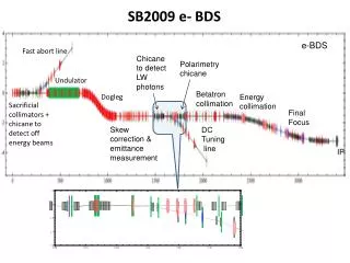
Details of the new layout Small (0.8m) shafts for laser wire and polarimeters On surface buildings with laser rooms Global Design Effort
Details of the new layout Small (0.8m) shaft for laser for downstream polarimeter. Transverse straight pass through rock to IR2 to another polarimeter. On surface buildings with laser rooms Tunnel “knee” to reduce volume of tapered tunnel (still straight path for multi-TeV is OK) Extraction line is shortened by 100m, relying more on beam sweeping to avoid water boiling and window damage (photons not swept, but their size is acceptably large) Global Design Effort
Details of the new layout Passages around the 5m muon wall (the magnetized walls penetrate into the tunnel by ~0.5m) needed for personnel access, equipment transportation and alignment. Passages are long enough, allowing installing extra muon wall (up to baseline 18m) if needed 5m wall Passages around the muon wall which is not installed initially, but can be installed in upgrade (up to baseline 9m), if the muon background is too high Global Design Effort
Details of the new layout Alcoves 4*6m, spaced at 100m for BDS equipment, PS, etc. Passages between beamlines 9m shaft for BDS access There is NO shaft at the end of the linac Global Design Effort
Details of the new layout Cavern 35*20m for tune-up beam dump water cooling system Caverns 35*20m for main beam dump water cooling system Global Design Effort