Download
1 / 32
360 likes | 1.06k Vues
Dye Sensitized Solar Cells. Group Meeting Presentation October 2, 2006. Introduction. With increasing human population and energy consumption; it is obvious that we need to find alternative sources of energy.

E N D
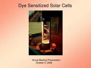
Dye Sensitized Solar Cells Group Meeting Presentation October 2, 2006
Introduction With increasing human population and energy consumption; it is obvious that we need to find alternative sources of energy. Solar energy is inexhaustible and free, atleast for the next few billion years!! The challenge is to utilize it efficiently and use it on much larger scale. Two basic attempts: Chemically approaching an artificial photosynthesis ( converting biomass to energy ) Solar Cells (photovoltaics) Solar cells are in use to a certain extent but the efficiency is not as desired. An alternative approach to solar cells are the Dye Sensitized Solar Cells.
Principle of the DSC Principle of operation of the dye-sensitized nanocrystalline solar cell. (The energy levels drawn match the redox potentials of the N3 sensitizer ground state and the iodide/triiodide couple) Photoexcitation of the sensitizer (S) is followed by electron injection into the conduction band of a semiconductor oxide film. The dye molecule is regenerated by the redox system, which itself is regenerated at the counter electrode by electrons passed through the load.
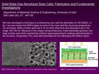
Film Morphology The first DSC made in the laboratory used a titanium sheet covered with a high-surface-area "fractal" TiO2 film that was produced by a sol-gel method. The most widely used nanocrystalline semiconductor oxide electrode in the DSC as an electron collector to support a molecular or QD sensitizer is TiO2, although other wide-band semiconductor oxides such as ZnO, SnO2, or Nb2O5 have also been employed. These semiconductor oxides have high surface area which helps in sensitizer binding and efficient solar harvesting. The 50-70% porosityallows facile diffusion of redox mediators within the film to react with surface-bound sensitizers. The density of unfilled acceptor states can be widely and reversibly tuned in energy for increasing light to electrical energy conversion efficiencies.
Scanning electron micrograph of a sintered mesoscopic TiO2 film supported on an FTO glass. Nanoparticles of the oxide are deposited, for example, by screen printing onto a glass or flexible plastic support covered with a transparent conducting layer of fluorine-doped tin dioxide (FTO) or tin-doped indium oxide (ITO). Each particle is then coated with a monolayer of sensitizer or a QD formed by self-assembly from a staining solution.
Charge-Carrier Transport For the operation of the DSC it is necessary that charges injected in the nanoparticles should be screened on the mesoscopic scale by the surrounding electrolyte, facilitating electron percolation. This electron charge screening is done by the cations in the electrolyte. Local screening of electrons injected from a conducting support into a nanocrystalline oxide film.
The electron motion in the conduction band of the mesoscopic oxide film is coupled with an interfacial electron-transfer reaction and with ion diffusion in the electrolyte. The movement of electrons in the conduction band of the mesoscopic films is accompanied by the diffusion of charge-compensating cations in the electrolyte layer close to the nanoparticle surface. The cations screen the Coulomb potential of the electrons avoiding the formation of uncompensated local space charge. Electron motion through a network of mesoscopic semiconductor particles.
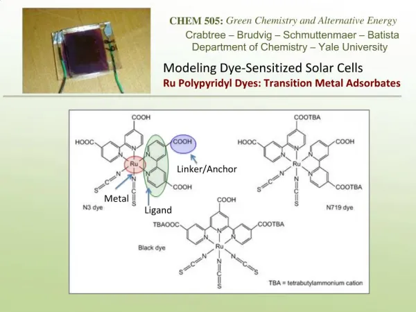
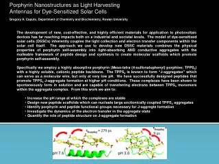
Light Harvesting by Dye-Derivatized Mesoscopic Oxide Films The absorption of light by a monolayer of dye is weak since the area occupied by one molecule is much larger than its optical cross section for light capture. Good photovoltaic efficiency cannot be obtained by use of a flat semiconductor surface but rather by use of the porous, nanostructured film of very high surface roughness . Structure of the ruthenium sensitizers RuL3 (yellow) cis-RuL2(NCS)2 (red) and RuL'(NCS)3 (green) where L = 2,2'-bipyridyl-4,4'-dicarboxylic acid and L' = 2,2',2' '-terpyridyl-4,4,'4' '-tricarboxylic acid. The lower part of the picture shows nanocrystalline TiO2 films loaded with a monolayer of the respective sensitizer. The film thickness is 5 µ m.
The conduction band of the large-band-gap semiconductor oxide accepts the electrons from the electronically excited sensitizer. The electrons injected into the solid percolate very rapidly across the TiO2 layer (a TiO2 film of 10µm thickness is crossed in 10 ms.) Recent work has focused on the molecular engineering of suitable ruthenium compounds, which are known for their excellent stability. cis-Di(thiocyanato)bis(2,2'-bipyridyl)-4,4'-dicarboxylate) ruthenium(II), coded as N3 or N-719 dye depending on whether it contains four or two protons, was found to be an outstanding solar light absorber and charge-transfer sensitizer. Charge injection from the electronically excited sensitizer into the conduction band of the semiconductor is in competition with other radiative and non-radiative processes. The deactivation of the electronically excited state of the sensitizer is generally very rapid. Typical kdeact values lie in the range from 103 to 1010 s-1. To achieve a good quantum yield, the rate constant for charge injection should be at least 100 times higher than kdeact i.e. in the picosecond range.
In recent years sensitizers have been developed that satisfy these requirements. These dyes incorporate functional groups such as, carboxylate, hydroxamate, or phosphonate moieties that anchor the sensitizer to the oxidesurface. Interfacial electron transfer involving a ruthenium complex bound to the surface of TiO2 via a carboxylated bipyridyl ligand.
These sensitizers also effect an enhanced electronic coupling of the sensitizer LUMO with the conduction band of the semiconductor. The quantum yield of charge injection generally exceeds 90%. The formation of the oxidized sensitizer and conduction band electrons due to heterogeneous charge transfer from the excited ruthenium complex into the conduction band of the oxide is resolved on a femtosecond time scale. The time constant can be estimated as being definitely shorter than 20 fs, corresponding to a rate constant kinj > 5 × 10¹³ s-1. Transient absorption signal for N-719 adsorbed on nanocrystalline titania (ο), (pump wavelength 535 nm; probe 860 nm).
Light-Induced Charge Separation • The next step of the conversion of light into electricity, a complete charge • separation must be achieved. • Thermodynamically, the recombination of the injected electron and the oxidized sensitizer is always downhill. • Methods/Processes Inhibiting The Recombination: • Sensitizer • For the N-719 ruthenium sensitizer, the forward injection is an extremely rapid process occurring in femtoseconds. By contrast, the back reaction of the electrons with the oxidized ruthenium complex involves a d orbital localized on the ruthenium metal whose electronic overlap with the TiO2 conduction band is small and is further reduced by the spatial contraction of the wave function upon oxidation of Ru(II) to Ru(III). • Thus, the electronic coupling element for the back reaction is 1-2 orders of magnitude smaller for the back electron transfer as compared to injection reducing the back reaction rate by the same factor.
The recombination process is characterized by a large driving force and small • reorganization energy, with the respective values for N-719 being 1.5 and 0.3 eV, • respectively. • This places the electron recapture in the inverted Marcus region, reducing its • rate by several orders of magnitude. • The three cases illustrated are for electron • transfer in • the normal region with - ΔGο< λ • the barrierless point where - ΔGο= λ • the inverted region with - ΔGο > λ Free energy-coordinate curves illustrating the influence on the classical barrier to electron transfer of increasing - ΔG at fixed reorganization energy, λ .
Charge recombination is, furthermore, inhibited by the existence of an electric field • at the surface of the titanium dioxide film. • A surface field is established spontaneously by proton transfer from the carboxylic • acid groups of the ruthenium complex to the oxide surface, producing a charged • dipole layer. • The local potential gradient from the negatively charged sensitizer to the positively • charged oxide drives the injection on the desired direction. The same field also • inhibits the electrons from exiting the solid after injection has taken place. • Stepwise Electron Injection Light excitation results in an unprecedented electron "hopping" from the Ru to Rh to the semiconductor nanocrystallite. Under the experimental conditions studied, about 40% of the electrons that arrive at Rh were found to transfer electrons to TiO2, the rest recombined to Ru(III). This branching ratio presumably reflects different orientations of the compound on the TiO2 surface.
In solar cells, the photocurrent efficiency was rather low, mainly because of low charge injection yields. Nevertheless, the results suggest a general strategy to slow recombination between the injected electron and oxidized sensitizer. • Hole Hopping • Intramolecular "hole" transfer has been used to regenerate the ground • state of the Ru(II) chromophore at sensitized TiO2 interfaces. The first • compound reported to perform this function was • Ru(dcb)2(4-CH3-4'-CH2-PTZ-2,2'-bipyridine)2+, where PTZ is the electron donor • phenothiazine,
When attached to TiO2, MLCT excitation resulted in a new charge-separated state with an electron in TiO2 and an oxidized PTZ group, abbreviated PTZ+-Ru/TiO2(e-). Recombination of the electron in TiO2 with the oxidized PTZ to yield the ground state occurred with a rate constant of 3.6 × 10³ s-1. Excitation of a model compound that did not contain the PTZ donor, Ru(dcb)2(dmb)22+, where dmb is 4,4'-(CH3)2-bpy, under otherwise identical conditions gave rise to the immediate formation of a charge- separated state, TiO2(e-)-Ru(III), that recombined with an average rate constant of 3.9 × 10⁶ s-1.
Photoinduced processes occurring during photovoltaic energy conversion at the surface of the nanocrystalline titania films: Gray spheres: titania nanoparticles. Red dots: sensitizer. Green and blue dots: oxidized and reduced forms of the redox couple. • sensitizer (S) excitation by light; • (2) radiative and nonradiative deactivation of the sensitizer; • (3) electron injection in the conduction band, followed by electron trapping and • diffusion to the particle surface; • (4) recapture of the conduction band electron by the oxidized sensitizer (S+); • (5) recapture of the conduction band electrons by the oxidized form of the redox • couple regenerating the sensitizer and transporting the positive charge to the • counter electrode.
QD Sensitizers Semiconductor QDs can replace dyes as light-harvesting units in the DSC. Light absorption produces excitons or electron-hole pairs in the QD. The electron is subsequently injected in the semiconductor oxide support, while the hole is transferred to a hole conductor or an electrolyte present in the pores of the nanocrystalline oxide film. Efficient and rapid hole injection from PbS QDs into triarylamine hole conductors has been demonstrated, and IPCE (Incident Photon to Current Conversion Efficiency) values exceeding 50% have been obtained without attempting to optimize the collector structure and retard interfacial electron-hole recombination. QDs have much higher optical cross sections than molecular sensitizers, depending on the their size. However, they also occupy a larger area on the surface of the mesoporous electrode, decreasing the QD concentration in the film. Thus, the value of the absorption length is similar to that observed for the dye-loaded films. Recent discovery shows that multiple excitons can be produced from the absorption of a single photon by a QD via impact ionization if the photon energy is 3 times higher than its band gap. The challenge now is to find ways to collect the excitons before they recombine.
Present Embodiments of the DSC The most widely used sensitizer for the DSC has been cis-Ru(SCN)2L2 (L = 2,2'-bipyridyl-4,4'-dicarboxylate), abbreviated as N3.The redox system employed to regenerate the dye and transport the positive charges to the counter electrode has been the iodide/triiodide couple dissolved in an organic electrolyte or in a room-temperature ionic liquid. ( Very promising results have been obtained also with cobalt(II) complexes. )
Photovoltaic Performance Conversion of light to electric current by mesoscopic solar cells sensitized with the N-719 ruthenium dye. The IPCE is plotted as a function of the excitation wavelength. Absorption spectrum of the N-719 dye in ethanol featuring two MLCT bands.
The IPCE values exceed 80% in the wavelength range near the absorption maximum of the sensitizer, which is located around 530 nm. Even at 700 nm, where the absorption of light by the dye is weak, the IPCE value is still about 50%. This performance is much greater than expected because such large-area junctions (400 nm particle size) should do poorly in photovoltaic energy conversion in the presence of defects at the disordered surface, enhancing the recombination of photogenerated charge carriers. These extraordinary findings are due to the specific kinetic features of the interfacial charge-transfer processes summarized below. Dynamics of redox processes involved in the conversion of light to electric power by DSCs.
The initial events of electron injection and dye regeneration leading to photoinduced charge separation occur on a femto- to nanosecond or microsecond time scale, while the redox capture of the electron by the oxidized relay and the electron migration across the nanocrystalline film take place within milliseconds or even seconds. The square root of the product of the electron lifetime and diffusion coefficient corresponds to the diffusion length of the electron. If the latter is greater than the film thickness, all of the photogenerated carriers will be collected. A certified overall power conversion efficiency of 10.4% was attained in 2001. A new record efficiency of over 15.75% was achieved recently. These cells have been made using a tandem configuration of the DSCs where different sensitizers absorb different region of the solar radiation. Dye-Sensitized cells with their high efficiencies are certainly getting competitive with the conventional solar devices, a commercially even more significant parameter is the dye lifetime achieved under working conditions. A stability test during 12 000 h of continuous full-intensity light exposure has confirmed that this system does not exhibit any inherent instability, in contrast to amorphous silicon, which undergoes photodegradation.
Recently, heteroleptic ruthenium complexes such as the K-19 dye have been introduced, which because of the extension of π conjugation on one of the bipyidyl ligands shows enhanced light absorption in the visible region. Excellent stability results under both long-term heat stress and light soaking have been obtained with these sensitizers.
Large-Scale Field Tests and Commercial Developments !! Konarka in the U.S.A., Aisin Seiki in Japan, RWE in Germany, and Solaronix in Switzerland, are actively pursuing the development of new products. DSCs are also used in building integrated photovoltaic elements such as electric-power-producing glass tiles. The Australian company Sustainable Technologies International has produced such tiles on a large scale for field testing and the first building has been equipped with a wall of this type.
Electroluminescence and Photovoltaic Response in Ionic Junctions Diffusion of electronic charge across a pn junction sets up a built-in potential, which allows current to flow preferentially in one direction (rectification). Rectification is also observed in junctions of ionic conductors, where a built-in potential arises from diffusion of anions (N) and cations (P) across a membrane. Examples in nature; bilayer membranes. Ionic transition metal complexes, such as [Ru(bpy)3]2+(PF 6–)2,where bpy is 2,2'-bipyridin is an example of an ionic conductor. The [Ru(bpy)3]2+ ion is an intrinsic semiconductor with a negligible concentration of mobile electrons and holes at room temperature due to a large HOMO-LUMO gap. An identifying feature of these materials is the mobile counter ions (PF 6–), which redistribute under the application of an applied bias and assist the injection of electronic charge.
Another example is the molecule 9,10-diphenylanthracene-2-sulfonate with sodium counter ions (DPAS–Na+) which has been used as a water-soluble fluorescence probe and for the generation of electrogenerated chemiluminescence in solution. In analogy to semiconductors, ionic conductivity can be classified as N-type in materials such as [Ru(bpy)3]2+(PF 6–)2, where the anions are the predominant carriers of ionic current, and P-type in materials such as DPAS–Na+, where the opposite is true. Because both N-type and P-type ionic conductors are available, ionic (PN) junctions can be fabricated in direct analogy to conventional semiconductor electronic (pn) junctions. This has been achieved using the technique of soft-contact lamination. A DPAS–Na+ film was deposited on a glass substrate with patterned indium tin oxide (ITO) electrodes. A [Ru(bpy)3]2+(PF 6–)2 film was deposited on a polydimethylsiloxane (PDMS) substrate with patterned Au electrodes. The two substrates were brought together, laminating the two organic layers to yield the structure ITO/DPAS–Na+//[Ru(bpy)3]2+(PF 6–)2/Au
Structure of the PN junction. • (B) Detail of the junction area. • (C) Relevant energy levels at the junction before • (dotted lines) and after (solid lines) ion diffusion. • The arrows in (B) indicate the direction in • which the counter ions diffuse to form the • junction when the two layers are brought in • contact. Structure and energetics of the PN junction.
The PN junctions show intense light emission under forward bias, with a luminance of 500 cd/m2 at 5 V. Their spectral response reveals that emission arises from the [Ru(bpy)3]2+(PF 6–)2 side of the junction. Electroluminescence spectra of the various devices
Illumination of the junctions resulted in a photovoltaic response. Under 100 mW/cm2 excitation from a halogen lamp, an open circuit voltage of 0.45 V and a short-circuit current density of 0.15 µA/cm2 were measured Photovoltaic response of the PN junction
Conclusion; In 1839, Edmund Becquerel, a French experimental physicist, discovered the photovoltaic effect. Scientists have come a long way from there; the mechanisms for interfacial charge separation and recombination are now understood in considerable molecular detail and are applied towards the improvement of solar cells. A significant future challenge is to intercept these states to drive reactions that produce useful fuels. Future prospects for solar energy conversion with coordination compounds anchored to semiconductor surfaces appear to be very bright.
References: • Gratzel, M. Inorg. Chem. 2005, 44, 6841. • Meyer, G. J. Inorg. Chem.2005, 44, 6852. • Mallouk, T. E.; Hoertz, P. G. Inorg. Chem.2005, 44, 6828. • Nakade, S.; Kubo, W.; Saito, Y.; Kanzaki, T.; Kitamura, T.; Wada, Y.; Yanagida, • S. J. Phys. Chem. B2003, 107. • Plass, R.; Pelet, S.; Kruger, J.; Gratzel, M.; Bach, U. J. Phys. Chem. B2002, 106, • 7578. • Nozik, A. J. Quatum dot solar cells. Next Gener. Photovoltaics2004, 196. • Liska er al. 2006, 88, 203103. • Marcus, R. A. 1992, Nobel Lecture. • Bernards, D. A.; Samuel, F. T.; Hector, D. A.; George, G. M. Science,2006, 313, • 1416.