Asynchronous Pipelines
Asynchronous Pipelines. Author: Peter Yeh Advisor: Professor Beerel. Motivation. Can we reduce asynchronous pipelines communication overhead while hiding precharge time? Can we have cycle time in asynchronous pipelines as fast, if not faster, than best synchronous counterparts.

Asynchronous Pipelines
E N D
Presentation Transcript
Asynchronous Pipelines Author: Peter Yeh Advisor: Professor Beerel
Motivation • Can we reduce asynchronous pipelines communication overhead while hiding precharge time? • Can we have cycle time in asynchronous pipelines as fast, if not faster, than best synchronous counterparts. USC Asynchronous Group
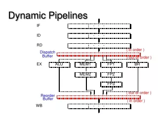
Motivation: System Performance • Fixed stage pipeline • Low pipeline usage: Low latency is critical • High pipeline usage: Cycle time is the limiting factor to generate new outputs as fast as possible • Flexible stage pipeline • With zero forward overhead and short cycle time, we can achieve a given desired throughput with fewer stages USC Asynchronous Group
Motivation: System Performance • Pipelines with loop dependencies • Optimal cycle time is the sum of latency around the loop • Pipelining is required to ensure precharge/reset is not in the critical path • Our scheme requires less pipeline stages to achieve same performance USC Asynchronous Group
Introduction • Asynchronous pipeline schemes using Taken Detector (TD) • Best use in coarse-grained pipelines • Two schemes targeting different requirements (a possible third SI scheme as well) USC Asynchronous Group
Outline • Background review • Sutherland • Ted William • Renaudin • Martin • Taken pipeline • Performance comparison • Conclusion USC Asynchronous Group
Definition • Stage: A collection of logic that is precharged or evaluated at the same time • Cycle: The time it takes for a stage to start next evaluation from the current one • Forward Latency: The time it takes between the start of the evaluation of current stage to next stage USC Asynchronous Group
Background Outline • Sutherland’s Micropipeline scheme • Ted William’s PS0 and PC0 pipeline schemes • Renaudin’s DCVSL pipeline scheme • Martin’s deep pipeline scheme USC Asynchronous Group
Cd P C C C C C Pd Pd Pd Pd Pd REG REG REG REG REG REG C Pd Cd Cd Cd Cd Cd P P P P P Sutherland’s Micropipeline • Father of Asynchronous Pipeline. Presented in Turing Award lecture • Delay Insensitive A(out) c c R(in) LOGIC LOGIC LOGIC D(out) D(in) A(in) c R(out) USC Asynchronous Group
William’s PC0 • Speed Independent • Cycle Time (P) = 3tF +1tF +4tC+4tD • Forward Latency (Lf) = 1tF+1tD+1tC A(in) A(out) C1 C2 C3 R(out) R(in) Precharged Function Block F1 Precharged Function Block F1 Precharged Function Block F1 Precharged Function Block F2 Precharged Function Block F3 Precharged Function Block F3 Precharged Function Block F3 Precharged Function Block F3 D2 D1 D3 D(out) D(in) USC Asynchronous Group
PC0 Timing Diagram • The cycle time is shown in read arrows while the blue arrows show the precharge phase USC Asynchronous Group
Dependency Graph C2 F2 C3 F3 C4 F4 D2 D2 D2 C1 F1 C2 F2 C3 F3 D1 D2 D3 +1 Flat Dependency Graph +1 0 0 C F D -1 Folded Dependency Graph -1 0 0 C F D +1 +1 USC Asynchronous Group
William’s PC1 • Cycle Time (P) = 2tF +4tC+4tD • Forward Latency (Lf) = 1tF+2tC+1tD A(in) A(out) C1 C2 R(out) R(in) Precharged Function Block F1 C Latch Precharged Function Block F2 DB DA D2 D(in) D(out) USC Asynchronous Group
William’s PS0 • Not Speed Independent • Cycle Time (P) = 3tF +1tF +2tD • Forward Latency (Lf) = 1tF A(in) A(out) Precharged Function Block F1 Precharged Function Block F2 Precharged Function Block F3 D2 D1 D3 D(out) D(in) USC Asynchronous Group
PS0 Timing Diagram USC Asynchronous Group
PS0 Timing Assumption • The pipeline has to meet the following timing assoumption tF USC Asynchronous Group
Renaudin’s DCVSL Pipeline • Compare to Ted’s PC0 only • Use DCVSL exclusively • Introduce Latched DCVSL • Improve cycle time but not forward latency • Cycle Time (P) = 1tF+1tF+ 4tC +2tD • Forward Latency (Lf) = 1tF + 1tC +1tD USC Asynchronous Group
DCVS Logic Family DCVS Logic Latched DCVS Logic USC Asynchronous Group
More on DCVSL • Advantage • Fast, based on the dynamic domino type logic • Build-in Four-Phase handshaking • Robust completion sensing • Storage element • Disadvantage • Higher Complexity - increase in number of transistors and area • Higher Power dissipation USC Asynchronous Group
DCVS Pipeline • Cycle Time (P) = 1tF+1tF+4tC +2tD (2tF+4tC +2tD ) • Forward Latency (Lf) = 1tF +1tC +1tD R(in) A(out) C1 C2 C3 A(in) R(out) Precharged Function Block F1 Precharged Function Block F2 Precharged Function Block F3 D2 D1 D3 D(in) D(out) USC Asynchronous Group
DCVS Pipeline Timing Diagram USC Asynchronous Group
DCVS Dependency Graph • Cycle Time (P) = 1tF+1tF+4tC +2tD • Forward Latency (Lf) = 1tF +1tC +1tD +1 +1 0 0 C F D Folded Dependency Graph -1 -1 0 0 C F D +1 +1 USC Asynchronous Group
Martin’s Pipeline Schemes • Deep pipelining • Quasi Delay-Insensitive (QDI)No timing assumption • Based on different handshaking reshuffling • Best scheme has high concurrency which reduce control overhead • Control logic is more complex USC Asynchronous Group
2 1 3 Le Re Le Re Le Re L0 R0 L0 R0 L0 R0 L1 L1 L1 R1 R1 R1 Basic Asynchronous Handshaking Re Le Re Le R1 L1 L1 R1 • Reshuffling eliminates the explicit variable x • Large control overhead USC Asynchronous Group
2 1 3 Le Re Le Re Le Re L0 R0 L0 R0 L0 R0 L1 L1 L1 R1 R1 R1 Handshaking Reshuffling Re Le Re Le R1 L1 L1 R1 • Still wait for predecessor to reset before resetting itselflarger overhead for more inputs USC Asynchronous Group
2 1 3 Le Re Le Re Le Re L0 R0 L0 R0 L0 R0 L1 L1 L1 R1 R1 R1 Precharge-Logic Half-Buffer • Doesn’t wait for the predecessor to reset before it resets its outputs. Yet, the control logic wait for the reset of the predecessor only after current stage has reset Re Le Re Le R1 L1 L1 R1 USC Asynchronous Group
2 1 3 Le Re Le Re Le Re L0 R0 L0 R0 L0 R0 L1 L1 L1 R1 R1 R1 Precharge-Logic Full-Buffer • Allows the neutrality test of the output data to overlap with raising the left enables • Complex control logic, requires extra state variable Re Le Re Le en en R1 L1 L1 R1 USC Asynchronous Group
Martin’s PCHB Full-adder USC Asynchronous Group
Martin’s Pipeline in General Le Le • The Cycle time is limited by the properties of QDI • Next stage has to finish precharge before the current stage can evaluate next input Control Control Control Precharged Function Block F1 Precharged Function Block F2 Precharged Function Block F3 Re D2 D1 D3 D(out) D(in) USC Asynchronous Group
Performance Analysis on PCFB • Control logic can be seen as completion detection (D) plus C-element (C) • Reshuffling of handshaking just changes the degree of the concurrency but it doesn’t affect the best case performance analysis • Cycle Time (P) = 3tF+1tF+2tC +2tD • Forward Latency (Lf) = 1tF USC Asynchronous Group
Outline • Background review • Sutherland • Ted William • Renaudin • Martin • Taken pipeline • Performance comparison • Conclusion USC Asynchronous Group
Taken Pipeline • Use of Taken Detector • Two schemes to satisfy different requirements • Both are not speed independent USC Asynchronous Group
Initial Idea • Precharge: only when next stage has taken the current result • Evaluation: only when next stage has precharged • Similar idea to Martin’s pipeline schemes USC Asynchronous Group
Further Observation • Precharge • We can precharge the current stage as soon as the first level logic of next stage has evaluatednext stage has taken the result • Evaluate • Evaluation can be started as soon as the guarded N-transistor in the first level logic of next stage has turned off USC Asynchronous Group
Relax Precharge (RP) Constraint • Current stage can precharge as soon as the first level logic of next stage has evaluated: Next stage has Taken the result • Current stage can evaluate as soon as the first level logic of next stage has precharged, blocking the new result from passing through • No need for extra control logic except TD which is similar to completion detector USC Asynchronous Group
TD2 TD1 TD3 RP Pipeline Scheme • Cycle Time (P) = 2tF+ 1tF1+1tF1+2tTD • Forward Latency (Lf) = 1tF Precharged Function Block F1 Precharged Function Block F2 Precharged Function Block F3 D(in) D(out) USC Asynchronous Group
RP Timing Diagram USC Asynchronous Group
RP Timing Assumption • Easy to meet timing assumption USC Asynchronous Group
RP Timing Assumption Cont. • tF1iis the first level logic of stage i • tF2iis the logic after the first level of stage i • Assuming rising and falling of TD is the same USC Asynchronous Group
Relax Evaluation (RE) Constraint • Current stage can start the evaluation about the same time as the next stage turns off the guarded N-transistors in the first level logic • Requires general C-element, yet improve cycle time USC Asynchronous Group
TD2 TD1 TD3 RE Pipeline Scheme • TD can be skewed for fast evaluation detection • Cycle Time (P) = 2tF+ 1tF1+1tTD +1tC • Forward Latency (Lf) = 1tF + + + GC1 GC1 GC1 Precharged Function Block F1 Precharged Function Block F2 Precharged Function Block F3 D(in) D(out) USC Asynchronous Group
RE Timing Diagram USC Asynchronous Group
RE Timing Assumption 1 • Precharge constraint USC Asynchronous Group
RE Timing Assumption 2 • Evaluation constraint (Min Delay) USC Asynchronous Group
Issue in Fine-Grained Pipelines • In a fine-grained pipeline, such as Martin’s single gate pipeline, RE scheme may require buffering due to process variation • Buffering is necessary because of second timing assumption, next gate (stage) may not have turned off N-stack before the result from current stage reaches it USC Asynchronous Group
Taken Detector (TD) • Similar to Completion Detector • Detect both evaluation and precharge • Inputs are the output of first level logic of each stage USC Asynchronous Group
C Precharged Function Block F2a Precharged Function Block F1 Precharged Function Block F3 D(in) D(out) Precharged Function Block F2b TD3 TD2a TD1 TD2b Datapath Merging & Splitting • Datapath merging and splitting can be done similar to William’s style USC Asynchronous Group
Outline • Background review • Sutherland • Ted William • Renaudin • Martin • Taken pipeline • Performance comparison • Conclusions USC Asynchronous Group
Comparison of RE and Synchronous Skew Tolerant • Assuming 4 stages pipeline, stage 1-4, and 4 phases clocking • Synchronous: • Stage 1 starts next evaluation after stage 4 starts evaluation • Asynchronous: • Stage 1 starts next evaluation after we detect the completion of the first level logic of stage 3 USC Asynchronous Group
Comparison Assumptions • It is a balanced pipeline—all stages have equal evaluation time • Precharge time is same as evaluation time USC Asynchronous Group