Alternating Current Circuits
Chapter 28. Alternating Current Circuits. AC Circuit. An AC circuit consists of a combination of circuit elements and an AC generator or source The output of an AC power source is sinusoidal and varies with time according to the following equation Δ v = Δ V max sin ω t


Alternating Current Circuits
E N D
Presentation Transcript
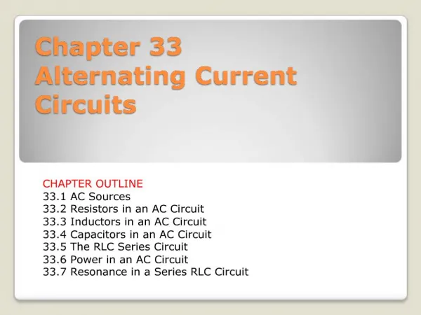
Chapter 28 Alternating Current Circuits
AC Circuit • An AC circuit consists of a combination of circuit elements and an AC generator or source • The output of an AC power source is sinusoidal and varies with time according to the following equation Δv = ΔVmaxsinωt • Δv: instantaneous voltage • ΔVmax is the maximum voltage (amplitude) of the generator • ωis the angular frequency of the AC voltage
Resistors in an AC Circuit • Consider a circuit consisting of an AC source and a resistor ΔvR = ΔVmax sin ωt • ΔvR is the instantaneous voltage across the resistor • The instantaneous current in the resistor is • The instantaneous voltage across the resistor is also given as ΔvR = ImaxR sin ωt
Resistors in an AC Circuit • The graph shows the current through and the voltage across the resistor • The current and the voltage reach their maximum values at the same time • The current and the voltage are said to be in phase • The direction of the current has no effect on the behavior of the resistor
Resistors in an AC Circuit • The rate at which electrical energy is dissipated in the circuit is given by • i: instantaneous current • The heating effect produced by an AC current with a maximum value of Imax is not the same as that of a DC current of the same value • The maximum current occurs for a small amount of time
rms Current and Voltage • The rms current is the direct current that would dissipate the same amount of energy in a resistor as is actually dissipated by the AC current • Alternating voltages can also be discussed in terms of rms values • The average power dissipated in resistor in an AC circuit carrying a current I is
Ohm’s Law in an AC Circuit • rms values will be used when discussing AC currents and voltages • AC ammeters and voltmeters are designed to read rms values • Many of the equations will be in the same form as in DC circuits • Ohm’s Law for a resistor, R, in an AC circuit ΔVR,rms = Irms R • The same formula applies to the maximum values of v and i
Capacitors in an AC Circuit • Consider a circuit containing a capacitor and an AC source • Kirchhoff’s loop rule gives: • ΔvC: instantaneous voltage across the capacitor
Capacitors in an AC Circuit • The voltage across the capacitor lags behind the current by 90° • The impeding effect of a capacitor on the current in an AC circuit is called the capacitive reactance (measured in ohms):
Chapter 28Problem 22 A capacitor and a 1.8-kΩ resistor pass the same current when connected across 60-Hz power. Find the capacitance.
Inductors in an AC Circuit • Consider an AC circuit with a source and an inductor • Kirchhoff’s loop rule gives: • ΔvL: instantaneous voltage across the inductor
Inductors in an AC Circuit • The voltage across the inductor always leads the current by 90° • The effective resistance of a coil in an AC circuit is called its inductive reactance (measured in ohms):
LC Circuit A capacitor is connected to an inductor in an LC circuit Assume the capacitor is initially charged and then the switch is closed Assume no resistance and no energy losses to radiation The current in the circuit and the charge on the capacitor oscillate between maximum positive and negative values
LC Circuit With zero resistance, no energy is transformed into internal energy Ideally, the oscillations in the circuit persist indefinitely (assuming no resistance and no radiation) The capacitor is fully charged and the energy in the circuit is stored in the electric field of the capacitor Q2max / 2C No energy is stored in the inductor The current in the circuit is zero
LC Circuit The switch is then closed The current is equal to the rate at which the charge changes on the capacitor As the capacitor discharges, the energy stored in the electric field decreases Since there is now a current, some energy is stored in the magnetic field of the inductor Energy is transferred from the electric field to the magnetic field
LC Circuit Eventually, the capacitor becomes fully discharged and it stores no energy All of the energy is stored in the magnetic field of the inductor and the current reaches its maximum value The current now decreases in magnitude, recharging the capacitor with its plates having opposite their initial polarity The capacitor becomes fully charged and the cycle repeats The energy continues to oscillate between the inductor and the capacitor
LC Circuit The total energy stored in the LC circuit remains constant in time Solution:
LC Circuit The angular frequency, ω, of the circuit depends on the inductance and the capacitance It is the natural frequency of oscillation of the circuit The current can be expressed as a function of time:
LC Circuit Q and I are 90°out of phase with each other, so when Q is a maximum, I is zero, etc.
Energy in LC Circuits The total energy can be expressed as a function of time The energy continually oscillates between the energy stored in the electric and magnetic fields When the total energy is stored in one field, the energy stored in the other field is zero
Energy in LC Circuits In actual circuits, there is always some resistance Therefore, there is some energy transformed to internal energy Radiation is also inevitable in this type of circuit The total energy in the circuit continuously decreases as a result of these processes
Chapter 28Problem 27 An LC circuit with a 20-µF capacitor oscillates with period 5.0 ms. The peak current is 25 mA. Find (a) the inductance and (b) the peak voltage.
The RLC Series Circuit • The resistor, inductor, and capacitor can be combined in a circuit • The current in the circuit is the same at any time and varies sinusoidally with time
The RLC Series Circuit • The instantaneous voltage across the resistor is in phase with the current • The instantaneous voltage across the inductor leads the current by 90° • The instantaneous voltage across the capacitor lags the current by 90°
Phasor Diagrams • Because of the different phase relationships with the current, the voltages cannot be added directly • To simplify the analysis of AC circuits, a graphical constructor called a phasor diagram can be used • A phasor is a vector rotating CCW; its length is proportional to the maximum value of the variable it represents • The vector rotates at an angular speed equal to the angular frequency associated with the variable, and the projection of the phasor onto the vertical axis represents the instantaneous value of the quantity
Phasor Diagrams • The voltage across the resistor is in phase with the current • The voltage across the inductor leads the current by 90° • The voltage across the capacitor lags behind the current by 90°
Phasor Diagrams • The phasors are added as vectors to account for the phase differences in the voltages • ΔVL and ΔVC are on the same line and so the net y component is ΔVL - ΔVC
Phasor Diagrams • The voltages are not in phase, so they cannot simply be added to get the voltage across the combination of the elements or the voltage source • is the phase angle between the current and the maximum voltage • The equations also apply to rms values
Phasor Diagrams ΔVR = Imax R ΔVL = Imax XL ΔVC = Imax XC
Impedance of a Circuit • The impedance, Z, can also be represented in a phasor diagram • φ: phase angle • Ohm’s Law can be applied to the impedance ΔVmax = Imax Z • This can be regarded as a generalized form of Ohm’s Law applied to a series AC circuit
Chapter 28Problem 29 Find the impedance at 10 kHz of a circuit consisting of a 1.5-kΩ resistor, 5.0-µF capacitor, and 50-mH inductor in series.
Power in an AC Circuit • No power losses are associated with pure capacitors and pure inductors in an AC circuit • In a capacitor, during 1/2 of a cycle energy is stored and during the other half the energy is returned to the circuit • In an inductor, the source does work against the back emf of the inductor and energy is stored in the inductor, but when the current begins to decrease in the circuit, the energy is returned to the circuit
Power in an AC Circuit • The average power delivered by the generator is converted to internal energy in the resistor Pav = Irms ΔVR,rms ΔVR, rms= ΔVrms cos Pav = Irms ΔVrms cos • cos is called the power factor of the circuit • Phase shifts can be used to maximize power outputs
Resonance in an AC Circuit • Resonance occurs at the frequency, ω0, where the current has its maximum value • To achieve maximum current, the impedance must have a minimum value • This occurs when XL = XC and
Resonance in an AC Circuit • Theoretically, if R = 0 the current would be infinite at resonance • Real circuits always have some resistance • Tuning a radio: a varying capacitor changes the resonance frequency of the tuning circuit in your radio to match the station to be received
Chapter 28Problem 28 A series RLC circuit has R = 75 Ω, L = 20 mH, and resonates at 4.0 kHz. (a) What’s the capacitance? (b) Find the circuit’s impedance at resonance and (c) at 3.0 kHz.
Damped LC Oscillations The total energy is not constant, since there is a transformation to internal energy in the resistor at the rate of dU/dt = – i2R Radiation losses are still ignored The circuit’s operation can be expressed as:
Damped LC Oscillations Solution: Analogous to a damped harmonic oscillator When R = 0, the circuit reduces to an LC circuit (no damping in an oscillator)
Transformers • An AC transformer consists of two coils of wire wound around a core of soft iron • The side connected to the input AC voltage source is called the primary and has N1 turns • The other side, called the secondary, is connected to a resistor and has N2turns • The core is used to increase the magnetic flux and to provide a medium for the flux to pass from one coil to the other
Transformers • The rate of change of the flux is the same for both coils, so the voltages are related by • When N2 > N1, the transformer is referred to as a step up transformer and when N2 < N1, the transformer is referred to as a step downtransformer • The power input into the primary equals the power output at the secondary
Chapter 28Problem 36 You’re planning to study in Europe, and you want a transformer designed to step 230-V European power down to 120 V needed to operate your stereo. (a) If the transformer’s primary has 460 turns, how many should the secondary have? (b) You can save money with a transformer whose maximum primary current is 1.5 A. If your stereo draws a maximum of 3.3 A, will this transformer work?
Answers to Even Numbered Problems Chapter 28: Problem 14 V = (325 V) sin[(314 s−1)t]
Answers to Even Numbered Problems Chapter 28: Problem 26 22 to 190 pF
Answers to Even Numbered Problems • Chapter 28: • Problem 30 • 95 Hz • 18 kΩ
Answers to Even Numbered Problems Chapter 28: Problem 32 500 W