Download
1 / 17
170 likes | 385 Vues
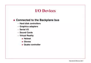
External I/O Control - Using the GPIO Unit to Control the External I/O Devices. Speaker: Yu-Ju Cho 卓余儒 Advisor: Prof. An-Yeu Wu 吳安宇教授 National Taiwan University Adopted from Chang Gung University. Goal of This Lab.

E N D
External I/O Control-Using the GPIO Unit to Control the External I/O Devices Speaker: Yu-Ju Cho 卓余儒 Advisor: Prof. An-Yeu Wu 吳安宇教授 National Taiwan University Adopted from Chang Gung University
Goal of This Lab • Understand the operation mechanism of a GPIO (General Purpose Input/Output) unit • Design a GPIO and verify the design on the Logic Module • Learn the method of connecting an external I/O device to the ARM Integrator Platform • Employ the GPIO to control the external I/O device.
ARM PrimeCell GPIO • General Purpose Input/Output (GPIO) • The GPIO is an AMBA slave module that connects to the APB. • Which has 16 pins organized into two 8-bit ports.
Functional Overview • The data direction register is 8 bits wide, and is programmed to select whether each individual input/output pin is configured as an input or an output. • The data register is 8 bits wide, and is used to read the value input on those pins are configured as input, and program the value output on the output pins.
Data Direction Register • GPIOPADDR is the port A data direction register. • Bits set in GPIOPADDR will set the corresponding pin in PORT A to be an output. • Clearing a bit configures the pin to be an input. • GPIOPBDDR is the port B data direction register. • Bits cleared in GPIOPBDDR will set the corresponding pin in PORT B to be an output. • Setting a bit configures the pin to be an input
AMBA APB interface • The AMBA APB group narrow-bus peripherals to avoid loading the system bus, and provides an interface using memory-mapped registers.
Memory Address • The base address of the PrimeCell GPIO is not fixed, and may be different for any particular system. But the offset of any particular register is fixed
GPIO Operation • Write Operation Setup Cycle ENABLE Cycle
GPIO Operation (cont.) • Read Operation Setup Cycle ENABLE Cycle
Connect an external device to the ARM Integrator Remember to series resistances
Pin Assignment for Port A • NET GPIO1XPA<0> LOC=b20; • NET GPIO1XPA<1> LOC=a21; • NET GPIO1XPA<2> LOC=b21; • NET GPIO1XPA<3> LOC=a22; • NET GPIO1XPA<4> LOC=b22; • NET GPIO1XPA<5> LOC=c22; • NET GPIO1XPA<6> LOC=d22; • NET GPIO1XPA<7> LOC=e22;
Pin Assignment for Port B • NET GPIO1XPB<0> LOC=a23; • NET GPIO1XPB<1> LOC=b23; • NET GPIO1XPB<2> LOC=c23; • NET GPIO1XPB<3> LOC=d23; • NET GPIO1XPB<4> LOC=e23; • NET GPIO1XPB<5> LOC=a24; • NET GPIO1XPB<6> LOC=b24; • NET GPIO1XPB<7> LOC=c24;
References • ARM PrimeCell General Purpose Input/Output (PL060) Technical Reference Manual (ARM DDI 0142B). • Zong-xin Lin, “Design of an ARM-based System-on-Chip for Real-time QRS Detection in Electrocardiogram,” master thesis, Department of Electrical Engineering, Chang Gung University, Taiwan, June 2003. • Xilinx Logic Module Schematics:lm_xcv600e_revc.pdf