Download
1 / 17
280 likes | 545 Vues
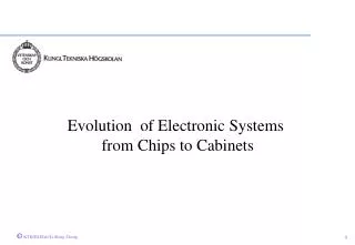
Evolution of Electronic Systems from Chips to Cabinets. Course Review: High-Speed Digital System Design. 10 9 10 8 10 7 10 6 10 5 10 4 10 3 10 2. DRAM Memories. 256M. 4G. f300 mm. 1G. 10G. Microprocessors. 64M. f200 mm. 6G Hz. 3.5GHz. 16M. f150 mm. 2.5G Hz. 4M.

E N D
109 108 107 106 105 104 103 102 DRAM Memories 256M 4G f300mm 1G 10G Microprocessors 64M f200mm 6G Hz 3.5GHz 16M f150mm 2.5G Hz 4M Pentium 4 Pentium III f125mm 1M ITRS’99 Pentium II Xeon Celeron Devices per chip 256k Pro 80386 Pentium f100mm 80486 64k 80286 16k 68020 f75mm 4k 32032 6800 8086/8088 1k 8048 8080 Z80 4004 Desk calculator 2.0mm 1.2mm 500nm 250nm 130nm 70nm 8.0mm 5.0mm 3.0mm 1.2mm 800nm 350nm 180nm 100nm 50nm 1970 1974 1978 1982 1986 1990 1994 1998 2002 2006 2010 Years SSI MSI VLSI LSI ULSI GSI Moore’s Law and Technology Sacling … the performance of an IC, including the number components on it, doubles every 18-24 months with the same chip price ... - Gordon Moore - 1960
Microelectronics Evolution: SoC Paradigm Yesterday’s chip is today’s function block!
The Electronic Package Evolution: Traditional Package Package inductance: 1 - 20 nH • DIL (Dual In Line) • Low pin count • Large • PGA (Pin Grid Array) • High pin count (up to 400) • Previously used for most CPU’s • PLCC (Plastic leaded chip carrier) • Limited pin count (max 84) • Large • Cheap • SMD • QFP (Quarter Flat pack) • High pin count (up to 300) • small • Cheap • SMD
The Electronic Package Evolution: New Types of Package • BGA (Ball Grid Array) • Small solder balls to connect to board • small • High pin count • Cheap • Low inductance • CSP (Chip scale Packaging) • Similar to BGA • Very small packages Package inductance: 1 - 5 nH
-------- Termination Resistor Integral R Integral L Integral C Decoupling Cap Ceramic or PWB SOP: Microelectronics for the 21st Century YESTERDAY TODAY MCM MCM Discrete Packaging System-on-Package-on-Board (SOPOB) Integrated Digital Packaging SOB / MCM/DCA Wafer-level Test & Burn-in & I/O SLIM Package SOP SLIM
The Role of Packaging Different functional roles: • Power distribution: supply power current to devices/chips • Signal distribution: connecting electrical and optical signals from chip to chip or to external devices • Heat dissipation: remove heat from the devices/chips, make system reliable • Package protection: protect devices or chips from environmental or mechanical damages
Second-Level Packaging: From packaged chips on PCB to multichip packaging From TH-PCB package to SMT-PCB package to MCM integration Higher Performance, Mixed-Signal Integration, Lower Power Others: Reduce Cost: save expensive chip real-estate by reducing off-chip drivers: Lower Switching Noise (Ldi/dt): e.g. Lpin =5nH in PLCC pin Lpin =9pH in flip-chip bump
IBM S390 Servers Technology: Multi-Chip Module Packaging, 75 metal layers Module Size: 127mm x 127 mm Clock (MHz) On-Chip Off-Chip IBM S390/G5 500 300 IBM S390/G6 637 500 IBM z900 (S390/G7) 1100 < 700? Theoretical limitation of off-chip speed (Katopis, EPEP99): 700MHz. Future on-chip speed is > 3GHz Power: 1400 Watt @1GHz State-of-the-Art High Performance Systems f70mm With Flip-Chip Connection
Evolution of System Level Package: Multi-Chip Modules • System level package: from multi-level package to MCMs • Increase integration level of system (=smaller size) • Decrease loading of external signals (=higher performance, low power) • No packaging of individual chips (=lower inductance, higher frequency) RF/Analog Digital Today’s system MCM MCM Yesterday’s system Mixed-Signal
The Electronic Package Evolution: The Future, from MCM to SoP System-on-Package Multi-Chip Module • Integrated L,R,C instead of embedded L,R,C • Low inductance bonding instead of wire bonding • Technology fusion (RF, Digital, MEMS, Optical)
The System-on-Package Paradigm: The Goals • GOALS: • 10x Each • Performance • Cost • Reliability • Size SoP Tomorrow Time