RF Interlock Enhancements for Higher Intensities - Update
30 likes | 144 Vues
Implementing RF interlock strategies, installing filters, and upgrading hardware to enhance beam protection and reduce false alarms. Planned configuration for generating Beam Interlock Sum signal during next Technical Stop. Recent RF trip statistics and improvements outlined.

RF Interlock Enhancements for Higher Intensities - Update
E N D
Presentation Transcript
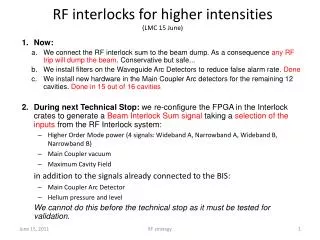
RF interlocks for higher intensities(LMC 15 June) RF strategy • Now: • We connect the RF interlock sum to the beam dump. As a consequence any RF trip will dump the beam. Conservative but safe... • We install filters on the Waveguide Arc Detectors to reduce false alarm rate. Done • We install new hardware in the Main Coupler Arc detectors for the remaining 12 cavities. Done in 15 out of 16 cavities • During next Technical Stop: we re-configure the FPGA in the Interlock crates to generate a Beam Interlock Sum signal taking a selection of the inputs from the RF Interlock system: • Higher Order Mode power (4 signals: Wideband A, Narrowband A, Wideband B, Narrowband B) • Main Coupler vacuum • Maximum Cavity Field in addition to the signals already connected to the BIS: • Main Coupler Arc Detector • Helium pressure and level We cannot do this before the technical stop as it must be tested for validation.
RF trip statistics since 30 May HV trips: RF trips:
Summary • Since 30 May, RF generated 10 beam dumps • Arc detector improvements would have avoided 6 of these • Connecting the interlock sum would have given an additional 5 beam dumps • including 1 Main Coupler vacuum interlock which is desirable to protect the coupler