Simulating Quartic
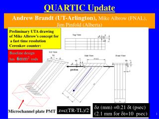
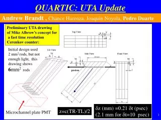
Simulating Quartic. James L Pinfold for the Quartic Group. The First Drawing. Each element of Quartic is comprised of a square section fused silica rod. Rod cross-section is 2 x 2 mm Maximum rod length is 10mm

Simulating Quartic
E N D
Presentation Transcript
Simulating Quartic James L Pinfold for the Quartic Group James L. Pinfold FP420 Meeting October 2005
The First Drawing • Each element of Quartic is comprised of a square section fused silica rod. • Rod cross-section is 2 x 2 mm • Maximum rod length is 10mm • Each rod is coated with vacuum deposited aluminium as a reflector and to provide optical isolation for each rod. All dimensions in millimetres James L. Pinfold FP420 Meeting October 2005
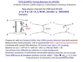
GEANT4 Simulation • A GEANT4 simulation is well underway (see GEANT4 produced graphics above. • The detector simulation includes: • Tracking of Cerenkov photons to the MCP-PMT through the medium. • Wavelength dedendent refractive index of the medium • Wavelength dependent attenuation of the photons • Wavelength dependent reflectivity of the aluminium reflector • Timing of photons from generation to the MCP-PMT • The effects of coupling grease (if necessary) James L. Pinfold FP420 Meeting October 2005
Simulating the MCP-PMT • Arrival time at the face of the MCP-PMT recorded • Implement wavelength dependence of the photo-cathode quantum efficiency. • Simulate PMT transit-time jitter by adding a normally distributed random time jitter with the appropriate standard deviation and to the arrival time • Simulate the layout of the anode pad readout of the MCP-PMT. • We make the approximation that the MCP-PMT output voltage having reached a certain level triggers a discriminator – this level corresponds to a certain number of photons having arrived. The MCP-PMT is a micro channel plate equipped with a photocathode and (usually) a multi-anode readout James L. Pinfold FP420 Meeting October 2005
Typical MCP-PMT (Burle 85001-501 James L. Pinfold FP420 Meeting October 2005
Timescale • Detector simulation has been essentially completed • On November 14th work will continue with the inclusion of the MCP-PMT stage • By the end of November we should have a full simulation of the QUARTIC for various scenarios • We will the need to validate the simulation against an prototype. James L. Pinfold FP420 Meeting October 2005