Download
1 / 87
930 likes | 1.32k Vues
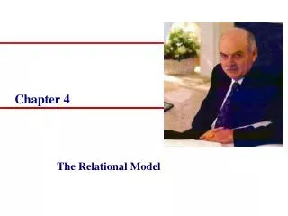
CHAPTER 4. Robot Dynamics. •. ( q , q ). L = K – P. Potential Energy. Lagrangian. Kinetic Energy. Dynamics. Joint Forces/Torque Joint Motion (End Effector Motion). LAGRANGIAN MECHANICS APPROACH

E N D
CHAPTER 4 Robot Dynamics
• (q, q) L = K – P Potential Energy Lagrangian Kinetic Energy Dynamics Joint Forces/Torque Joint Motion (End Effector Motion) LAGRANGIAN MECHANICS APPROACH – “Energy-based” approach to dynamics The Lagrangian & energy terms can be expressed in any convenient coordinate system (that will simplify the problem)
• where qi are the coordinates in which the kinetic & potential energy are expressed. qi = velocity Fi = corresponding Force torque in direction of qi generalized coordinates closed form solution • Dynamics The dynamics equations, in terms of the coordinates used to express the Kinetic & Potential Energy, are: Ref: B.J. Torby, “Advanced Dynamics for Engineers”, Halt Rinehart, 1984.
m (pt mass) • • • L K = ½ mv2 = ½ m(L)2 = ½ mL22 P = mg Lsin L = K – P • T • L = ½ mL22 – mg Lsin = ½ mL2(2) = mL2 = -mg Lcos • • • Dynamics Ex: 1 - DOF Robot
• •• T = mL2 + mg Lcos Dynamics T = Torque (in direction of ) Note: This can be derived from Fundamental laws of motion e.g. Newton’s eq. F = ma T = I leading to Newton-Euler formulation - recursive solution
ir Ti {i} {o} Base • • Note that ir is constant r = velocity of point • Kinetic Energy Velocity of a Point on the manipulator: given a point ir described with respect to link i, its position in base coords is r = Ti ir
• • • • • || r ||22 = r• r = Trace (r rT) • • • • Kinetic Energy
• • • Kinetic Energy of link i • • Ji = pseudo inertia matrix Kinetic Energy Kinetic Energy of a particle of mass dm located on link i at ir is
Kinetic Energy where all integrals are ∫link i and rT = [ ix iy iz 1 ]T Symmetric matrix
Recall That Ixx = ∫(y2 + z2) dm Iyy = ∫(x2 + z2) dm Izz = ∫(x2 + y2) dm Ixy = ∫ xy dm Ixz = ∫ xz dm Iyz = ∫ yz dm mx = ∫ x dm my = ∫ y dm mz = ∫ z dm Kinetic Energy
Then Kinetic Energy
• • Adding effect of actuators Kactuatori = ½ Iaiqi2 Iai = actuator inertia, rotational joint i = equivalent mass, translational joint i • Kinetic Energy The total kinetic energy of an N-joint manipulator is then neglecting actuator inertia
P = -mg• r ⊝ because g is opposite height above some reference zero r = position of center of mass of object g = gravity force vector Potential Energy
Ex: a mass m at r = 10i + 20j + 30k in a gravity field g = 0i + 0j + -32.2k has a P = 966 m The potential energy of a link whose center of mass is described by iri with respect to link i coord frame Ti is then Pi = -migT Tiiri reference is base frame where g = [ gx gy gz 0 ]T in base frame coords Total Potential Energy is Potential Energy
• • • Lagrangian Lagrangian L = K – P
• • • • change to k Dynamic Equations
• • • since for p > i, we have • • • Note that
•• •• • • • • used Trace (M) = Trace(MT)
• • • •
• • Interchanging dummy indices of summation j & k in 2nd term, & then combining with the first,
Therefore, • •• •• • •
•• •• • • OR Exchanging dummy summation indices p and i for i and j,
Model of Robot Dynamics •• •• • • Inertial Centripetal + Coriolis Gravity
OR F = D(q) q + C(q, q) + G(q) matrix-vector form •• • (Kinetic Energy) (Potential Energy) • • Note the diff indices ( p = max(i, j) ) compared to previous eqn for Fi can be verified to be correct
Simplifying the Dynamic Model Notation: Define
Rotational joint Translational joint where
In general F = D(q) q + C(q, q) + G(q) + b(q, q) where actuator inertia Iai are lumped into D(q) : dii dii + Iai b(q, q): frictional force/torque vector (damping + coulomb friction) OR F = D(q) q + H(q, q) H(q, q) = coupling vector that incorporates C(q, q), G(q) & b(q, q) •• • • • •• • • • • A more realistic dynamic model
relates Applied Joint Torque with Actuator Inputs U = [ Ui(t) ] (Voltage) L R Effective inertia + + V Vb Jeff _ _ m m Beff Effective viscous Coeff. Of friction (Damping) Ref: 1. Fu, Lee Gonzalez 2. Spong & Vidyasagar Actuator Dynamics
Gear Ratio: N m = N L m = N L m = N L L referred to motor shaft = L* L* = L JL • • Jm •• •• L L BL m m Bm •• • m = (Jmm + Bmm) + L Mechanical Eq. Actuator Dynamics Torque from = Torque on + Torque on Load motor shaft motor Referred to motor shaft
where Vb = KEm (Back Emf) KE in (Voltage constant of motor) m = KT i (torque delivered by motor) KT in (Torque constant of motor) (Note that if KE is in and KT is in , they are numerically equal, i.e. KE = KT) Actuator Dynamics Electrical Eqns:
•• • • m _ m m V(s) I KT + Vb KE Actuator Dynamics Summary:
For the case when load is just an inertia load: JL, L = JLL + BLL then •• • • •• • •• •• • Jeff Beff •• • m = Jeff m + Beff m on motor side where Actuator Dynamics
• m L m m V(s) I + KT _ KE Actuator Dynamics
_ m V + _ + KE • • Actuator Dynamics For Electro – Mechanical Systems, it is assumed that the electrical time constant L/R is much smaller than the Mechanical time constant Jm/Bm Setting L/R = 0 results in
•• • • • • Torque delivered on motor side Actuator Dynamics The robot dynamics equations incorporating actuator dynamics (ignoring L), in terms of robot (side) joint coords are:
• • •• • Actuator Dynamics Note Jm, Bm, KE, KT, N, R are different for each actuator-drive system
Summary of Properties & Characteristics of Inertia Coefficients • Inertia Matrix • Symmetric : dij = dji for all i and j • Positive definite : dii > 0 for all i • dij2 < diidjj for all i j • Self Inertia Coefficient (i = j) • joint i translational: • dii = mi + … + mN = constant • joint i rotational: • dii = (mi + … + mN)Kii2 = f(qi+1, … , qN)
Coeff of Coupling Summary of Properties & Characteristics of Inertia Coefficients Mutual Inertia Coefficients (for j > i) i = Transl, j = Transl: dij = (mj + … + mN) (zi-1• zj-1) = f(qi+1, … , qj-1) i = Transl, j = Rot: dij = (mj + … + mN) (zi-1x zj-1) • pj = f(qi+1, … , qN) i = Rot, j = Transl: dij = (mj + … + mN) (zj-1x zi-1) • pi = f(qi+1, … , qj-1, qj+1, … , qN) i = Rot, j = Rot: dij = (mj + … + mN) kij = f(qi+1, … , qN)
Centrifugal And Coriolis Coefficients • Cijm (Centrifugal & Coriolis coefficients) are • related to the inertial matrix through the • christoffel symbols: • These Christoffel symbols coupled with the • functional dependence of the inertial coef: • dij = f(qs+1, … , qN) where s = min(i, j) • simplify the formulation of the Centrifugal & • Coriolis coefs.
Cijj = 0 for i = j There are therefore N(N-1) independent centrifugal coefficients Centrifugal And Coriolis Coefficients
Centrifugal And Coriolis Coefficients • Furthermore • Cijj = f(qs+1, … , qN) where s = min(i, j) • Note that Cijj characterizes the effect of the velocity • of joint j on link i • Cjjj = 0 of course • Cijj is introduced by the coordinate dependence of the • inertial coefs. dij • when i > j, • Cijj = 0 if djj is independent of qi • when i < j, • Cijj = 0 if dij is independent of qj
Centrifugal And Coriolis Coefficients • Ex: Transl. joint j djj = constant, • dij = independent of qj Cijj = 0 • translational joint does not exert centrifugal forces on any link • centrifugal force is thus a unique characteristic of a rotational joint
Cijm = = f(qs+1, … , qN) where s = min(i, j) Centrifugal And Coriolis Coefficients • Coriolis Coefficients: • Based again upon the functional dependence of the inertial • coefficients, the coriolis coefs Cijm for j m are:
Centrifugal And Coriolis Coefficients • The symmetry of the inertial coefs leads to the • symmetry of the Coriolis coefs: • Cijm = Cimj • Cijm characterizes the effect of the coupling of • velocities of links j and m on link i • There appears to be N2(N-1)/2 independent • Coriolis coefs • This number is reduced to N(N-1)(N-2)/3 by • incorporating the non-interacting & reflective • coupling properties of the Coriolis coefs. • Non-Interacting Cijj = 0 for all j i • Reflective Coupling Cijm = - Cmji for all j i, m
Centrifugal And Coriolis Coefficients • Non-interacting property states that there is no Coriolis • force on a link due to the coupling of its velocity with • the velocity of an inner link. • Reflective coupling property states that the Coriolis coef • for link i, due to the coupling of velocities of links • j and m (j i, m), is equal & opposite to the Coriolis coef • for link m due to the coupled velocities of links j & i.
Coriolis forces account for the difference between • forces measured in rotating & non-rotating coord frames. • This diff. results from the observation that the energies of • a particle moving in 2 frames are diff. The rotation of • the first frame adds to a component which depends on the • coordinates of the particle & is proportional to angular • velocity of rotating frame. Centrifugal And Coriolis Coefficients
Centrifugal And Coriolis Coefficients • The practical significance of this fact is that a pair of links, • the inner of which is translational, does not exert Coriolis • forces on any link. • Consequently, the Coriolis force is a unique characteristic • of the coupling of the velocity of a rotating link to the • velocity of an outer link.
dot product Gi = mi• { i (g• zi-1) + i* (g • (zi-1 x pi)) } + ….. + mn• { i (g• zn-1) + i* (g • (zn-1 x pn)) }, for i,i+1,i+2,…N Gravitational Coefficients • For i = 0 (Rot. Joint), Gi = Gi(q1, … , qN) • For i = 1 (Trans. Joint), Gi = Gi(q1, … , qi-1) • There are 2 configurations of Practical Significance: • If link i translates in a direction to gravity field, • Gi = 0 since g • zi-1 = 0 (cylindrical robot last link) • If link i rotates about an axis parallel to gravity field, • Gi = 0 since g • (zi-1 x pi) = 0 (SCARA, 1st 2 links)
Hence, the gravitational coef of a joint characterizes the • work production of that joint in the gravity field. • In practice, counterbalances are introduced to reduce the • effect of gravity • A counterbalance is added to a link to alter its • mass distribution and reduce the corresponding • gravitational coef. Gravitational Coefficients