Download
1 / 61
630 likes | 772 Vues
The Failure of a Small Satellite and the Loss of a Space Science Mission. Richard B. Katz NASA Office of Logic Design richard.b.katz@nasa.gov. Objectives. About the SMEX/WIRE Mission How did the mission fail? Why did mission fail? Why do launchers and spacecraft fail?

E N D
The Failure of a Small Satellite and the Loss of a Space Science Mission Richard B. KatzNASA Office of Logic Design richard.b.katz@nasa.gov
Objectives • About the SMEX/WIRE Mission • How did the mission fail? • Why did mission fail? • Why do launchers and spacecraft fail? • Study critical resources: • Budget • Time • Reliability • Safety • Complexity • How we can prevent or minimize mishaps or failures?
Overview • Background and Introduction • How did the mission* fail? • Why did mission fail? • * SMEX/WIRE • Small Explorer • Wide Field Infrared Explorer
Who Am I? • Experience: • JPL • NASA GSFC • NASA Office of Logic Design • Design Engineer, Electrical • Galileo, Magellan, Cassini, ISTP, SIRTF, MGS, SMEX, MLA, LOLA, etc. • Research and Technology Development • Logic, FPGAs, Radiation, Design Techniques • Reviews, Failure Investigations • Cassini, HST, EOS-AM, AXAF, HETE-2, SIRTF, etc. • Small Explorer WIRE
Failure Examples (Simplified) Mars Climate Orbiter Units; Software reuse (1 comment) Mars Polar Lander 1 Line of Missing Software Ariane V/501 Operand Error, Unprotected Sea Launch Ground S/W Logic; Valve Config Intelsat VI “Two wires crossed” Terriers Inverted Sign IUS 21 Tape/Thermal Wrap Titan IV Data Entry Error SMEX/WIRE 1 Wire, Disable Buffer
1999 Payload Failures • 1. WIRE (NASA) • 2. TERRIERS (Boston University/AeroAstro) • 3. Abrixas (Germany) • 4. SACI 1 (Brazil) • All Small Scientific Satellites
Small Explorer (SMEX) Program Spacecraft Mass(kg) Launch Date Galileo 2,562 1989 SMEX 150-300 1992-1999 SMEX/WIRE 250 1999 UoSAT-12 325 1999 SNAP-1 7 2000
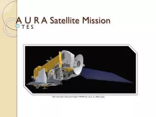
Wide-Field Infrared ExplorerProgrammatic PI: JPL Spacecraft: NASA Goddard Space Flight Center Instrument: Utah State University - SDL Launch: Orbital Science Corp. - Pegasus XL Cost: $75 million Duration: 4 Months
Wide-Field Infrared ExplorerTechnical Objective: Deep Infrared, Extragalactic Survey Detectors: Two 128 x 128 Si:As Arrays Telescope: 30 cm Cassegrain Cryostat: Solid Hydrogen; Dual Stage 7 K/12 K. Orbit: 540 kilometer
PYRO BOX LM117 REG +5VDC +5VDC +28V SPE 200 kHz +5VDC POR Relay FET PYRO CRYSTAL OSC 200 kHz ARM ARM SCS +5VDC FIRE FIRE POR R,C, 4093B A1020 POR PULSE Logic System Overview Spacecraft
WIRE Spacecraft Aperture Shade Star Tracker Modular Solar Array Composite Spacecraft
The WIRE Mission March 4th: Launch, Vandenberg Air Force Base/L-1011 T+9 min: Separation Nominal T+29 min: Antarctica Pass - Vent Command Xmitted T+79 min: NORAD Tracks 3 Objects, Including Cover T+99 min: Alaska Pass – Tumbling Eventually Spun up to 60 rpm T+36 Hrs: Cryogen Supply Exhausted March 8th: Mission Declared Lost
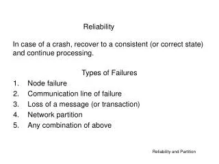
Root Cause of Failure (1) The root cause of a failure is the mechanism that directly caused the mishap. Significant contributing causes include events or conditions that could have been used to identify this condition as the phenomena has been understood. Contributing factors are other events or conditions that might have been able to prevent the mishap and should have been done significantly better.
Root Cause of Failure (2) The root cause of the WIRE mission loss are digital logic design errors in the instrument pyro electronics box. The transient performance of components was not adequately accounted for in its design. The failure was caused by two distinct mechanisms that, either singly or in concert, resulted in inadvertent pyrotechnic device firing during the initial pyro box power-up.
Requirements for Failure • Two Design Errors • Errors Not Caught In: • Analysis • Simulation • Design Reviews • Box Level Tests • Instrument Level Tests • Spacecraft Integration Tests • Spacecraft Systems Tests • Final Reviews
Why Did WIRE “Spin Up?” • Zero Thrust Vent - a “T.” • Vent Located To Minimize Pressure (Temperature). • One Side of “T” Pointed At Connector. • No Analysis of Exit Design During a Worst-Case Venting Scenario. • ACS Could Not Overcome Force • Spun Up To 60 RPM
"System" Perspective Spacecraft Instrument Spacecraft Power Electronics "PYRO Subsystem" Cover +28V BUS +28V Pyros PYRO BOX ARM Pyros Spacecraft Computer System (80386/387) FIRE Vent A 4th level of protection was an arming plug.
Basic Pyro Characteristics • NASA Standard Initiator, Type 1 (NSI-1) • No-Fire: 1 Amp and 1 Watt for 5 minutes • Bridgewire Impedance: ~ 1 • Fire Time: ~ 1 ms @ 5 amps
Cover Vent "Pyro Box" Perspective Instrument Pyro Box Power +28V • Pulse forming • Timing. • Lockouts. • Filtering. Logic Signal Arm • FPGA - Complex • FSM • Counters Logic Signal Fire Pyro Box is powered off during launch Multiple Pyro Functions
Regulator Circuit +5V OUT +28V IN
EM Regulator Performance +28V +5 VDC 5 ms/Div
Crystal Oscillator Characteristics It is known that crystal oscillators do not start immediately with the application of power. From Horowitz and Hill's The Art of Electronics, 2nd Edition: ... However, because of its high-resonant Q, a crystal oscillator cannot start up instantaneously, and an oscillator in the megahertz range typically takes 5-20 ms to start up; a 32 kHz oscillator can take up to a second (Q = 105). ... • Start up time for oscillators is sometimes not included in the specification. • - SMEX/WIRE Class S screening specification did not • include a start up time limit.
Example Oscillator Start Time 200 kHz +5 VDC T = 10 C 1 ms/Div Power Supply Rise Time = 1 ms for this example
Summary of Oscillator Start Times T = 10 C
Summary of Oscillator Start Times T = 10 C
Oscillator Startup on WIRE EM 23 ms +28V +5V 200 kHz Oscillator Output 5 ms/Div
Logic AnalysisAssuming Random Power Up Of Flip-Flops • Reset Flip-Flips • 3 Flip-Flops • At Least One Must Be A “0” To Be Safe • 7 Chances In 8 • ARMCNT Block • 14 Flip-Flops • All Must Be A “0” To Be Safe • One Chance In 16,384 • TIMECNT Block • 8 Flip-Flops • All Must Be A “0” To Be Safe • One Chance In 256 Note: Two Sides PFailure ~ 25%
FPGA and Drivers +5VDC +28 VDC 200 kHz POR Relay FET PYRO A1020 FPGA ARM FIRE
FPGA Implementation:Charge Pump And Isolation FETs HV Isolation FETs Module Output CHARGE PUMP Antifuse Module Input
A1020 Output TransientOverview Device Architecture Requires HV Isolation FETs ON Charge Pump Needs Time To Start, Bias HV FETs I/O May Power-up Uncontrolled Inputs May Source Current Outputs May Be Invalid Truth Tables Not Followed Documented In Actel App Notes; EEE Links, WWW Site Not Documented In Data Sheet
Output Transient - Investigation • Flight Pattern Obtained From SDL • Devices Programmed For Bench Test • A1020B’s (3) • Non-flight A1020 (1) • Flight A1020 (2) • Transients Observed On Critical Outputs • Critical Outputs May Be Latched High
A1020 Sample Transient Cover Arm VCC 5 ms/Div Device Had Been Powered Off For 2 Days
A1020 FPGA OutputTransient Summary • Longer power supply rise times • Increase the probability of the transient • Increase the size of the transient • Quick power cycles tend to eliminate transients • Long power-off times tend to increase the chance of a transient (memory effect). Now it was known how to test the Engineering Model
Instrument Level TestingFidelity of Spacecraft Power Electronics (SPE) Simulation
+28V Bench Power SupplyInstrument Level Testing Logic Begins To Function Relay Closes 10V / Div Relay Starts To Operate 50 ms / Div
Failure Demonstration on EM 13.5 msec A Side Power Input 5 A/Div 1.6 msec
EED Simulator - Input Stage Easy To “Trip” Low-Impedance Switched In After Delay
EED Simulator - Delay 23 ms CURRENT 1 A/Div +5VDC 2V/Div 10 ms/Div
Reporting Mechanism Not Used • Simulator Box Tripped In System Level Tests • Procedure Was To Reset The Simulator • Dispositioned "OK" By Similarity to Previous Mission With Different Hardware Set • Not Troubleshot in Depth • Design Engineer Not Involved • No Failure Report Written • Eliminated Reviews of Failure Report